Overview
There are four main types of data that the EFM ABB Totalflow driver is capable of getting from an ABB Totalflow device. These are:
- Application-Array-Register (AAR) data
- Alarm Data
- Event Data
- History Data
AARs are polled at a specified interval based on a poll rate and then made available via the OPC-UA interface. Alarms, events, and history are made available to MQTT Transmission to be published as immutable Record objects to an MQTT server. Typically these would be received by the MQTT Engine and MQTT Recorder modules running on a central Ignition Gateway and inserted into a database for later use or to be made available to other third party systems.
For the purposes of this document there are some definitions that are explained below.
EFM ABB TOTALFLOW → Settings
- Array-Register Definitions (Global)
- The global Array-Register definitions made available to the EFM ABB Totalflow module. They are uploaded to the Ignition instance either as individual INI files or as ZIP archives that contain INI files. Note that INI files are text files that are read by PCCU or WinCCU to determine how to display data within an application. These global Array-Register definitions can be referenced by the configurations of the individual ABB Totalflow devices that they apply to. A single Ignition Gateway may contain multiple global Array-Register definitions files that are used to configure Array-Register Templates (i.e. templates that contain array, register, access type, data type, and register name info) for available application types (enumerations).
- EFM Mappings
- Periodic Mappings
- The periodic mapping files are used for building up EFM Periodic History and Daily Records. They map various record fields to database column names so that user can adjust those column names to match requirements. Periodic mappings also allow to exclude certain record fields to be used. They are uploaded to the Ignition instance in the form of specifically formatted CSV files.
OPC-UA SERVER → Devices
- Totalflow Applications
- These is a list of applications (fields include respective name, slot number, enumeration, revision and type) that are currently installed on a Totalflow device. This list is obtained either by 'auto-discovery' process that takes place on configuration/restart or by importing specifically formatted CSV file.
- Array-Register Definitions (Device)
- These are a subset of the global Array-Register definition files that apply to a specific device.
- Array-Register Templates
- Array-Register templates are logical groupings of AARs. Generally Array-Register templates would be created so that instances of them can be used by specifying a poll group with application slot number.
- Poll Groups
- Poll groups use Array-Register templates in conjunction with application slot number to create a specific groups of register sets (i.e. sets of consecutive array registers) to be polled at a specified poll rate.
There are nine basic steps to getting all of the data available from a ABB Totalflow into Ignition
- Define/upload the global Array-Register definitions available for all Totalflow devices in this Ignition instance
- Define/upload the EFM Mappings for all Totalflow devices in this Ignition Instance
- Create the base device connection to the ABB Totalflow unit.
- If device is configured with the 'Enable auto-discovery' option turned on, wait for auto-discovery to complete. The device status will change from 'Auto-discovery' to 'Connected'. Go to the 'Totalflow Applications' configuration panel and verify that applications are there. Note that polling on all meter applications (i.e. TUBE applications) will be enabled by default. If device is configured with auto-discovery disabled, import application information from 'applications' CSV file that contains correct information on applications that run on a Totalflow device the driver is connected to. En example of such CSV file is shown below.
- If device is configured with the 'Add All Array-Register Definitions' option turned on, navigate to the 'Array-Register Definitions' configuration panel and verify that all global Array-Register definitions are added to this device definition automatically. If this configuration option turned off, manually add global Array-Register definitions that apply.
- If device is configured with the 'Auto-Generate Templates and Poll Group' option turned on, default Array-Register templates and default poll group will be generated. Navigate to the 'Array-Register Templates' and 'Poll Groups' configuration panels and verify templates have been created correctly. There are a few important points to note here:
- One default Array-Register template will be created per each application type (i.e. application enumeration) given that polling for at least one instance of this application type is enabled in the 'Totalflow Applications' panel.
- If there are no enabled applications at the time auto-discovery runs for the first time, no Array-Register templates will be created.
- If there are enabled applications but there are no Array-Register definitions applied to this device connection, or definitions that are applied have no applicable entries based of application enumeration; in this case, Array-Register templates will be created but those templates will have no entries. If applicable Array-Register definitions are added later, templates will be populated.
- Go to device configuration and disable all three options under the 'Auto Setup' category. Disabling auto-discovery will allow to get to the polling mode right after device connection is re-established. Disabling default templates auto-generation will allow to delete default templates and poll group without driver trying to regenerate them.
- Navigate to the 'Poll Groups' configuration panel and follow the 'Edit Poll Group Contents' link for the 'Default Poll Group'. Check the 'Enabled' box for each default poll group entry and click the 'Save' buttons twice: one time to save poll group entries, and another time to save poll groups. The device status will shortly change from 'Connected' to 'Polling'.
- Use Ignition Designer to pull tags into a tag provider.
Global Array-Register Definitions
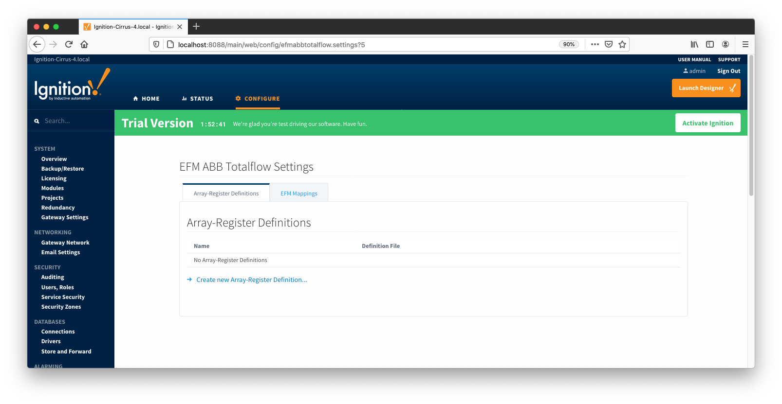
The ABB Totalflow driver module provides a configuration section to the Ignition Gateway. These can be seen in the Configure section of the Ignition Gateway web UI on the left panel near the bottom. Once in the configuration screen there will be a link to create new global Array-Register definitions. Click the link shown below to create a new one.
Note that it is the best practice to add global Array-Register definitions before any Totalflow device connections are defined. If Array-Register definition is added later, it needs to be added to a device connection manually. Even if device connection has the 'Add All Array-Register Definitions' option turned on, new global Array-Register definition will not be applied unless either added manually or device configuration is re-submitted.
When creating a new global Array-Register definition only a name and a Totalflow INI file(s) needs to be specified. The name can be any unique name that describes the Array-Register definitions included in submitted file(s). Totalflow INI files are configuration files for use with
PCCU and G2-G5 and NGC devices. Note that multiple Totalflow INI files need to be supplied in a ZIP archive.
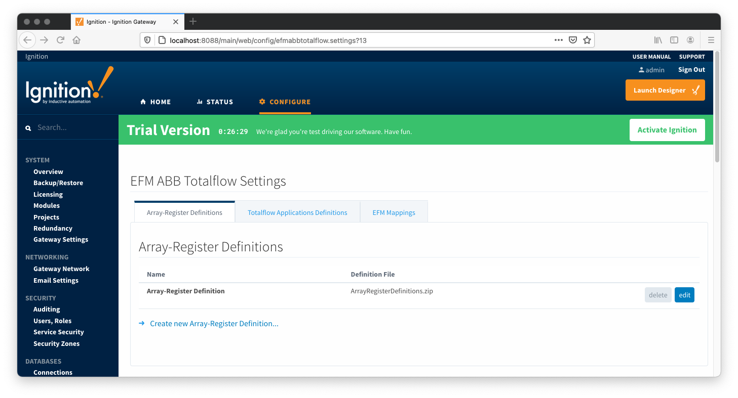
Note that definition archive file may contain lots of INI files. For example, the ArrayRegisterDefinitions.zip file shown above contains 1477 files. So it worth explaining how the ABB Totalflow driver selects which files to parse... When global Array-Register definitions are applied to a device connection, the driver uses application revision information obtained during the 'auto-discovery' process described later in this document, and selects INI file names that match application revision and variant numbers. As an example, below is application information obtained during the auto-discovery:
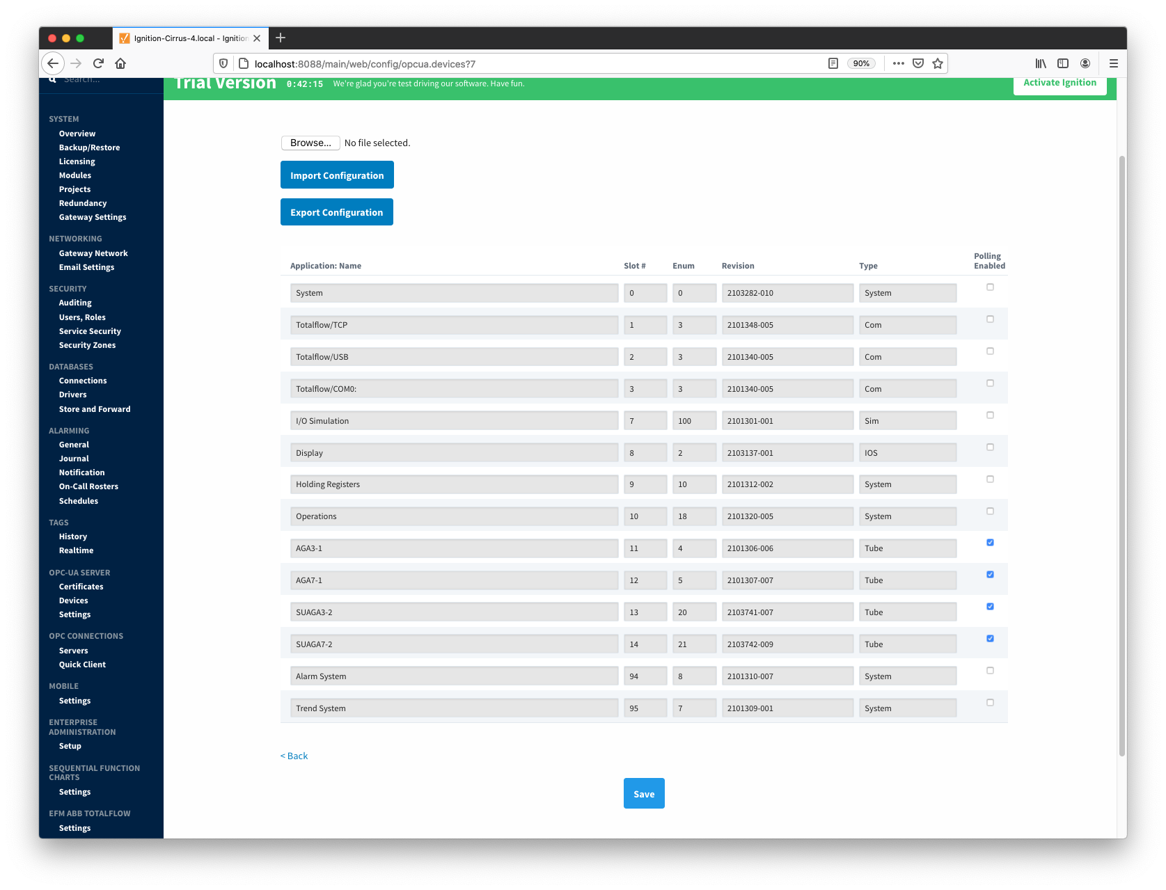
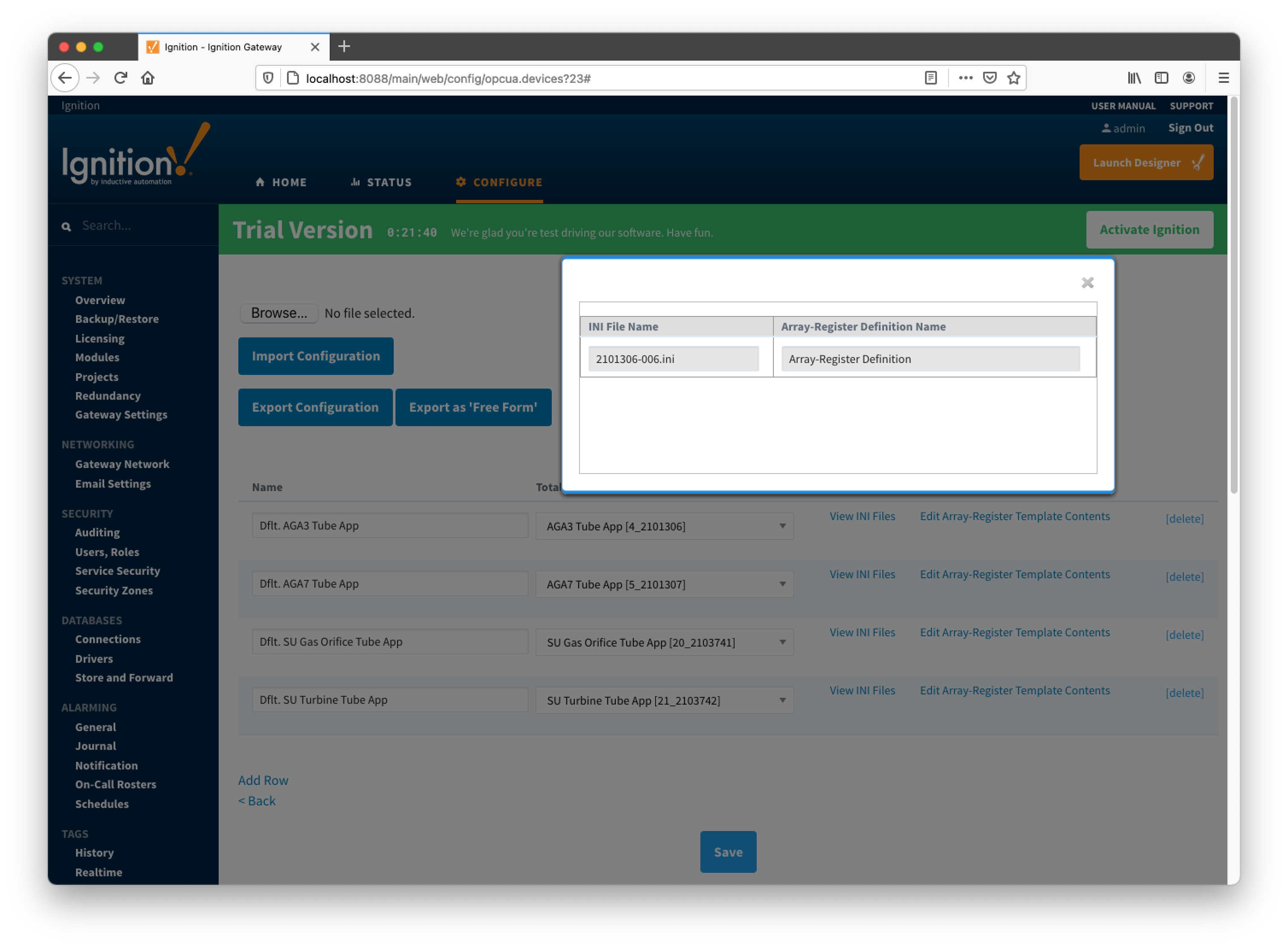
Note that revision number for the AGA3-1 meter application is 2101306-006; so the INI parser will look for the 2101306-006.ini file in submitted ZIP archive. If no direct match is found it will look for the another possible match based on the revision number (i.e. 2101306) and revision variant (i.e. 005 and lower). Also note that user has a way to check what INI file was picked by the driver as a source of Array-Register definitions. This information can be obtained form default Array-Register template generated by the driver by following the 'View INI Files' link as shown below:
Below is an example that shows a portion the 2101306-006.ini file for the AGA3 Tube Application:
[Live Analysis Data] ExtHlp 5000 Help 1171 #Columns=2,Description=300,Value=100
dsc:Last Update from THERMS;cmd:4.5.1;typ:S;rwa:1;
dsc:Last Update from Other Source;cmd:4.2.2;typ:D;rwa:1;
dsc:Heating Value Live @ Tb and Pb;cmd:4.3.45;typ:F;
dsc:Real Relative Density Live @ Tb and Pb;cmd:4.3.44;typ:F;
dsc:N2 Live;cmd:4.3.46;typ:F;
dsc:CO2 Live;cmd:4.3.47;typ:F;
dsc:Methane Live;cmd:4.3.51;typ:F;
dsc:H2S Live;cmd:4.3.48;typ:F;
dsc:H2O Live;cmd:4.3.49;typ:F;
dsc:Helium Live;cmd:4.3.50;typ:F;
dsc:Ethane Live;cmd:4.3.52;typ:F;
dsc:Propane Live;cmd:4.3.53;typ:F;
dsc:N-Butane Live;cmd:4.3.54;typ:F;
dsc:I-Butane Live;cmd:4.3.55;typ:F;
dsc:N-Pentane Live;cmd:4.3.56;typ:F;
dsc:I-Pentane Live;cmd:4.3.57;typ:F;
dsc:N-Hexane Live;cmd:4.3.58;typ:F;
dsc:N-Heptane Live;cmd:4.3.59;typ:F;
dsc:N-Octane Live;cmd:4.3.60;typ:F;
dsc:N-Nonane Live;cmd:4.3.61;typ:F;
dsc:N-Decane Live;cmd:4.3.62;typ:F;
dsc:Oxygen Live;cmd:4.3.63;typ:F;
dsc:Carbon Monoxide Live;cmd:4.3.64;typ:F;
dsc:Hydrogen Live;cmd:4.3.65;typ:F;
dsc:Argon Live;cmd:4.3.66;typ:F;
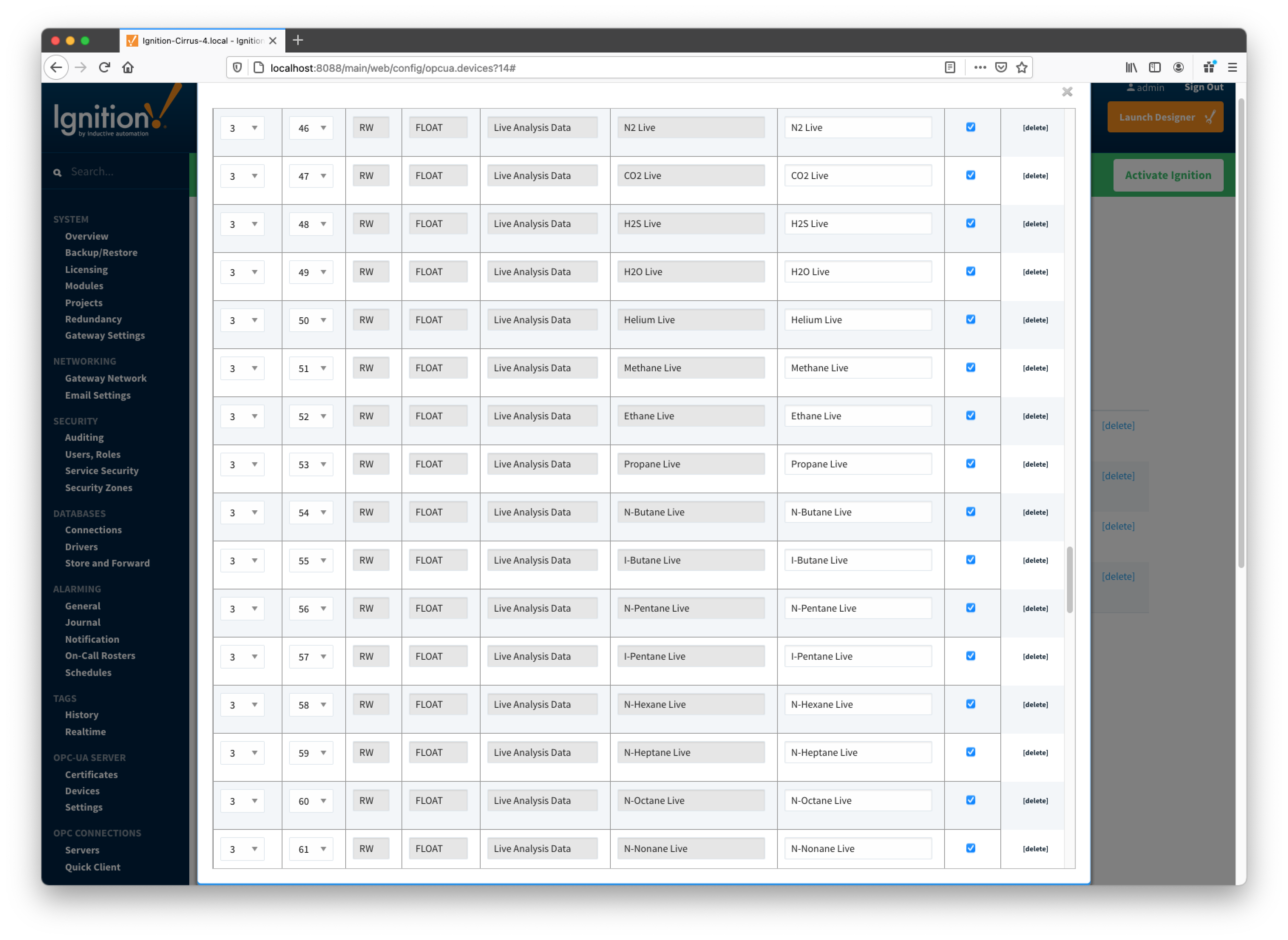
So the driver parses selected INI file and uses the info (i.e. Array-Register definitions) to generate Array-Register templates as shown below. Note how highlighted (bold) lines shown above correlate to Array-Register Templates shown below. Let's look at the 'dsc:N2 Live;cmd:4.3.46;typ:F;' line in more details... The point description (i.e. N2 Live) is being used as a tag name. The 'typ:F' is the data type (i.e. floating point). Finally, the '4.3.46' defines application, array, and register respectively. Note that 4 is not an application slot number, but application enumeration. As a result, a default Array-Register Template is generated by the driver for a specific application enumeration, and it contains all Array-Register points found in appropriate INI files.
EFM Mappings
Periodic Mappings
The periodic mapping files are used for building up EFM Periodic and Daily History Records. Each row of such file maps specific fields of LOG_PERIOD or DAILY records to a database column names. It also allows user to turn a database column off. In other words if column is disabled, respective filed will not be 'recordized'. These mappings are CSV files with the following values:
- Array Number
- Array number (i.e. 250 for the LOG_PERIOD_RECORD and 251 for DAILY_RECORD)
- Application Enumeration
- List of application enumerations this mapping entry should be applied. If empty, the mapping entry is applicable to any application.
- Record Field Offset
- Field offset within the record
- Data Type
- Description
- Column Name
- Enabled
- A flag that turns this field 'on/off'. In other words it defines if this field should be recordized.
Below is a mapping example for the LOG_PERIOD_RECORD:
# arrayNum, appEnum, offset, data type, description, column name, enabled
250,4|20,6,FLOAT,Average Differential Pressure,dp_avg,enabled
250,5|21,6,FLOAT,Pulse Counts,pulses,enabled
250,,10,FLOAT,Average Static Pressure,sp_avg,enabled
250,,14,FLOAT,Average Temperature,temp_avg,enabled
250,5|21,18,FLOAT,Uncorrected Volume,raw_vol,enabled
250,,22,FLOAT,Volume,volume,enabled
250,,26,FLOAT,Heating Value,heating_value,enabled
250,,30,UINT16,Flow Time,flo,enabled
250,,32,UINT16,Period Time,flo_rate,enabled
An example of the periodic mapping file can be found here: MeterPeriodicMapping.csv
The Periodic Mappings tab shows all uploaded Periodic Mapping files.
Main Properties