Overview
There are four main types of data that the EFM ABB Totalflow driver is capable of getting from an ABB Totalflow device. These are:
- Application-Array-Register (AAR) data
- Alarm Data
- Event Data
- History Data
AARs are polled at a specified interval based on a poll rate and then made available via the OPC-UA interface. Alarms, events, and history are made available to MQTT Transmission to be published as immutable Record objects to an MQTT server. Typically these would be received by the MQTT Engine and MQTT Recorder modules running on a central Ignition Gateway and inserted into a database for later use or to be made available to other third party systems.
For the purposes of this document there are some definitions that are explained below.
EFM ABB TOTALFLOW → Settings
- Array-Register Definitions (Global)
- The global Array-Register definitions made available to the EFM ABB Totalflow module. They are uploaded to the Ignition instance either as individual INI files or as ZIP archives that contain INI files. Note that INI files are text files that are read by PCCU or WinCCU to determine how to display data within an application. These global Array-Register definitions can be referenced by the configurations of the individual ABB Totalflow devices that they apply to. A single Ignition Gateway may contain multiple global Array-Register definitions files that are used to configure Array-Register Templates (i.e. templates that contain array, register, access type, data type, and register name info) for available application types (enumerations).
- Totalflow Applications Definitions (Global)
- The global Totalflow Applications Definitions are uploaded to the Ignition instance as individual CSV files and contain the following information about Totalflow applications:
- Enumeration number
- Name
- Type
- An optional flag (SU) that indicates that this is a 'Selectable Unit' application
- Part number(s)
- EFM Mappings
- Periodic Mappings
- The periodic mapping files are used for building up EFM Periodic and Daily History records. They map various record fields to database column names so that user can adjust those column names to match requirements. Periodic mappings also allow to exclude certain record fields to be used. They are uploaded to the Ignition instance in the form of specifically formatted CSV files.
OPC-UA SERVER → Devices
- Totalflow Applications
- This is a list of applications (fields include respective name, slot number, enumeration, revision and type) that are currently installed on a Totalflow device. This list is obtained either by 'auto-discovery' process that takes place on configuration/restart or by importing specifically formatted CSV file.
- Totalflow Applications Definitions (Device)
- These are a subset of the global Totalflow Applications Definition files that apply to a specific device.
- Array-Register Definitions (Device)
- These are a subset of the global Array-Register definition files that apply to a specific device.
- Array-Register Templates
- Array-Register templates are logical groupings of AARs. Generally, Array-Register templates would be created so that instances of them can be used by specifying a poll group with application slot number.
- Poll Groups
- Poll groups use Array-Register templates in conjunction with application slot number to create a specific groups of register sets (i.e. sets of consecutive array registers) to be polled at a specified poll rate.
There are eleven basic steps to getting all of the data available from a ABB Totalflow into Ignition
- Define/upload the global Array-Register definitions available for all Totalflow devices in this Ignition instance.
- Define/upload the global Totalflow applications definitions available for all Totalflow devices in this Ignition instance. Note that this step is optional since lots of application definitions are provided by the driver by default.
- Define/upload the EFM Mappings for all Totalflow devices in this Ignition Instance.
- Create the base device connection to the ABB Totalflow unit.
- If device is configured with the 'Enable auto-discovery' option turned on, wait for auto-discovery to complete. When auto-discovery is completed, the device status changes from 'Auto-discovery' to 'Connected'. Go to the 'Totalflow Applications' configuration panel and verify that applications are there. Note that polling on all meter applications (i.e. TUBE applications) will be enabled by default. If device is configured with auto-discovery disabled, import application information from a 'Totalflow Applications' CSV file that contains correct information on applications instantiated on a Totalflow device the driver is connected to.
- If device is configured with the 'Add All Totalflow Application Definitions' option turned on, navigate to the 'Totalflow Applications Definitions' configuration panel and verify that all global applications definitions are added to this device definition automatically. If this configuration option turned off, manually add global applications definitions that apply.
- If device is configured with the 'Add All Array-Register Definitions' option turned on, navigate to the 'Array-Register Definitions' configuration panel and verify that all global Array-Register definitions are added to this device definition automatically. If this configuration option turned off, manually add global Array-Register definitions that apply.
- If device is configured with the 'Auto-Generate Templates and Poll Group' option turned on, default Array-Register templates and default poll group will be generated. Navigate to the 'Array-Register Templates' and 'Poll Groups' configuration panels and verify templates have been created correctly. There are a few important points to note here:
- One default Array-Register template will be created per each application type (i.e. application enumeration) given that polling for at least one instance of this application type is enabled in the 'Totalflow Applications' panel.
- If there are no enabled applications at the time auto-discovery runs for the first time, no Array-Register templates will be created.
- If there are enabled applications but there are no Array-Register definitions applied to this device connection, or definitions that are applied have no applicable entries based of application enumeration; in this case, Array-Register templates will be created but those templates will have no entries. If applicable Array-Register definitions are added later, templates will be populated.
- Go to device configuration and disable all three options under the 'Auto Setup' category. Disabling auto-discovery will allow to get to the polling mode right after device connection is re-established. Disabling default templates auto-generation will allow to delete default templates and poll group without driver trying to regenerate them.
- Navigate to the 'Poll Groups' configuration panel and follow the 'Edit Poll Group Contents' link for the 'Default Poll Group'. Check the 'Enabled' box for each default poll group entry and click the 'Save' buttons twice: one time to save poll group entries, and another time to save poll groups. The device status will shortly change from 'Connected' to 'Polling'.
- Use Ignition Designer to pull tags into a tag provider.
Global Array-Register Definitions
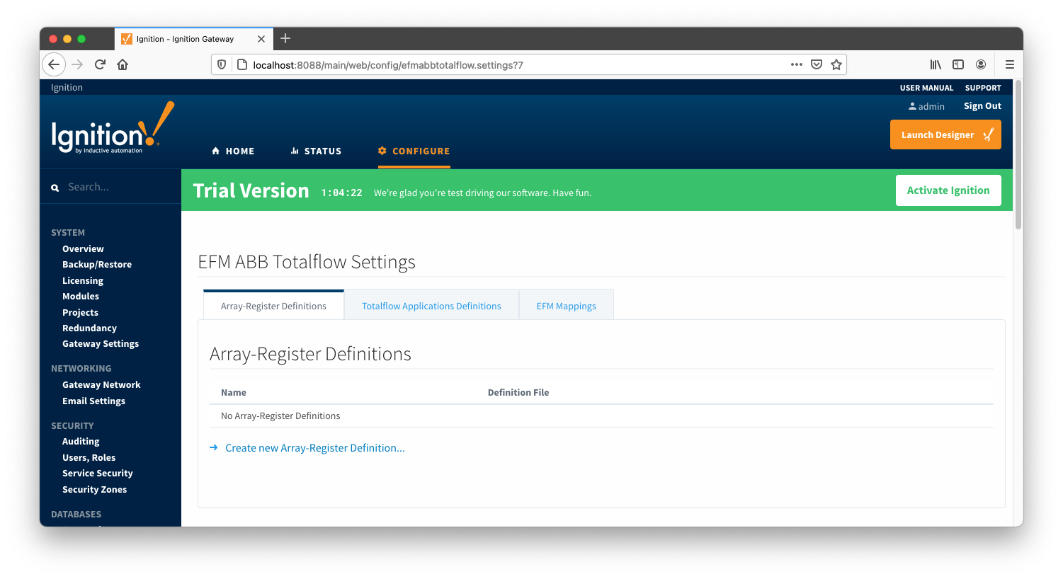
The ABB Totalflow driver module provides a configuration section to the Ignition Gateway. These can be seen in the Configure section of the Ignition Gateway web UI on the left panel near the bottom. Once in the configuration screen there will be a link to create new global Array-Register definitions. Click the link shown below to create a new one.
Note that it is the best practice to add global Array-Register definitions before any Totalflow device connections are defined. If an Array-Register definition is added later, it needs to be added to a device connection manually. Even if device connection has the 'Add All Array-Register Definitions' option turned on, new global Array-Register definition will not be applied unless either added manually or device configuration is re-submitted.
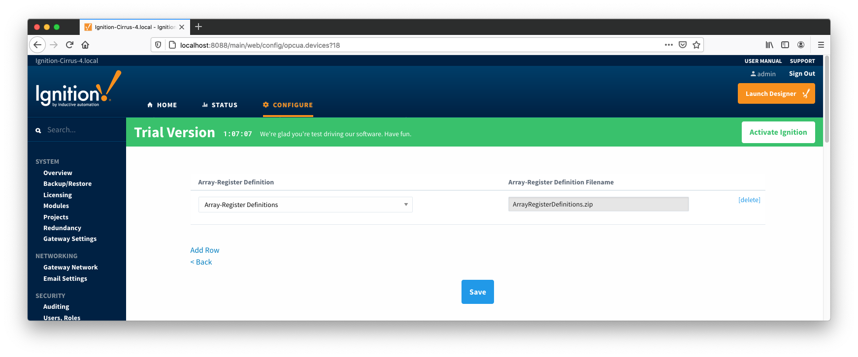
When creating a new global Array-Register definition, only a name and a Totalflow INI file(s) needs to be specified. The name can be any unique name that describes the Array-Register definitions included in submitted file(s). Totalflow INI files are configuration files for use with
PCCU and G2-G5 and NGC devices. Note that multiple Totalflow INI files need to be supplied in a ZIP archive.
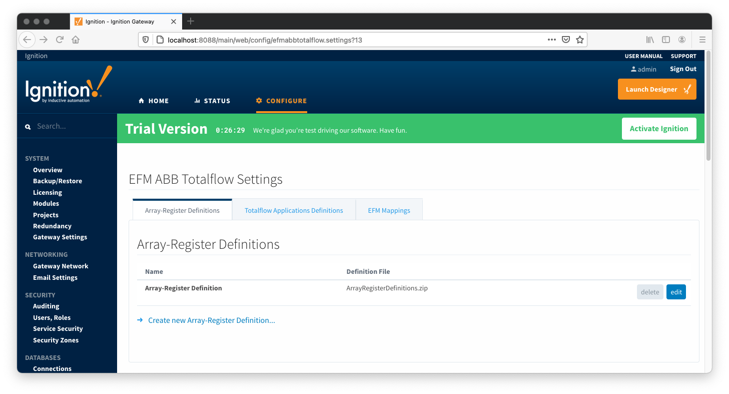
Note that definition archive file may contain lots of INI files. For example, the ArrayRegisterDefinitions.zip file shown above contains 1477 files. So it worth explaining how the ABB Totalflow driver selects which files to parse... When global Array-Register definitions are applied to a device connection, the driver uses application revision information obtained during the 'auto-discovery' process described later in this document and selects INI file names that match application revision and variant numbers. As an example, below is application information obtained during the auto-discovery:
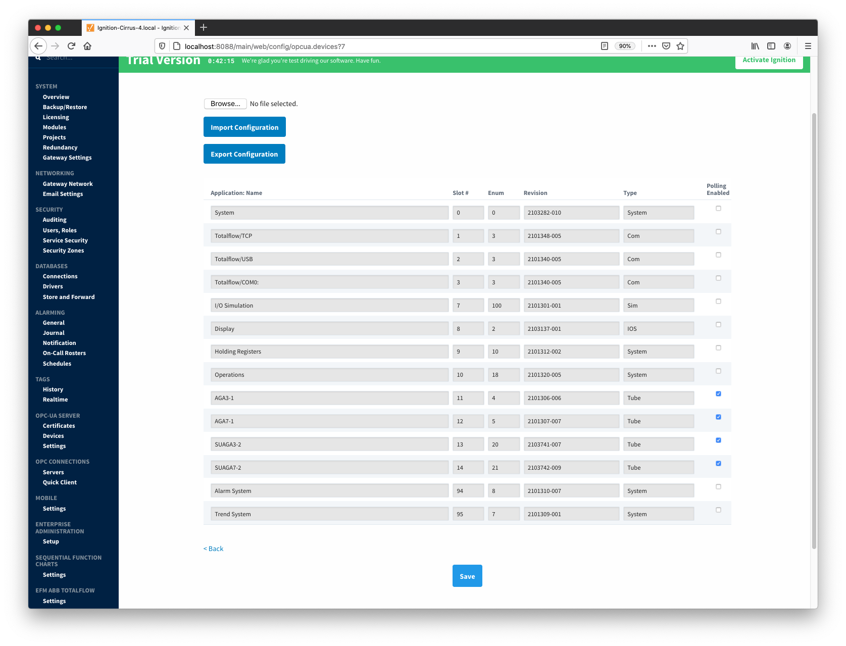
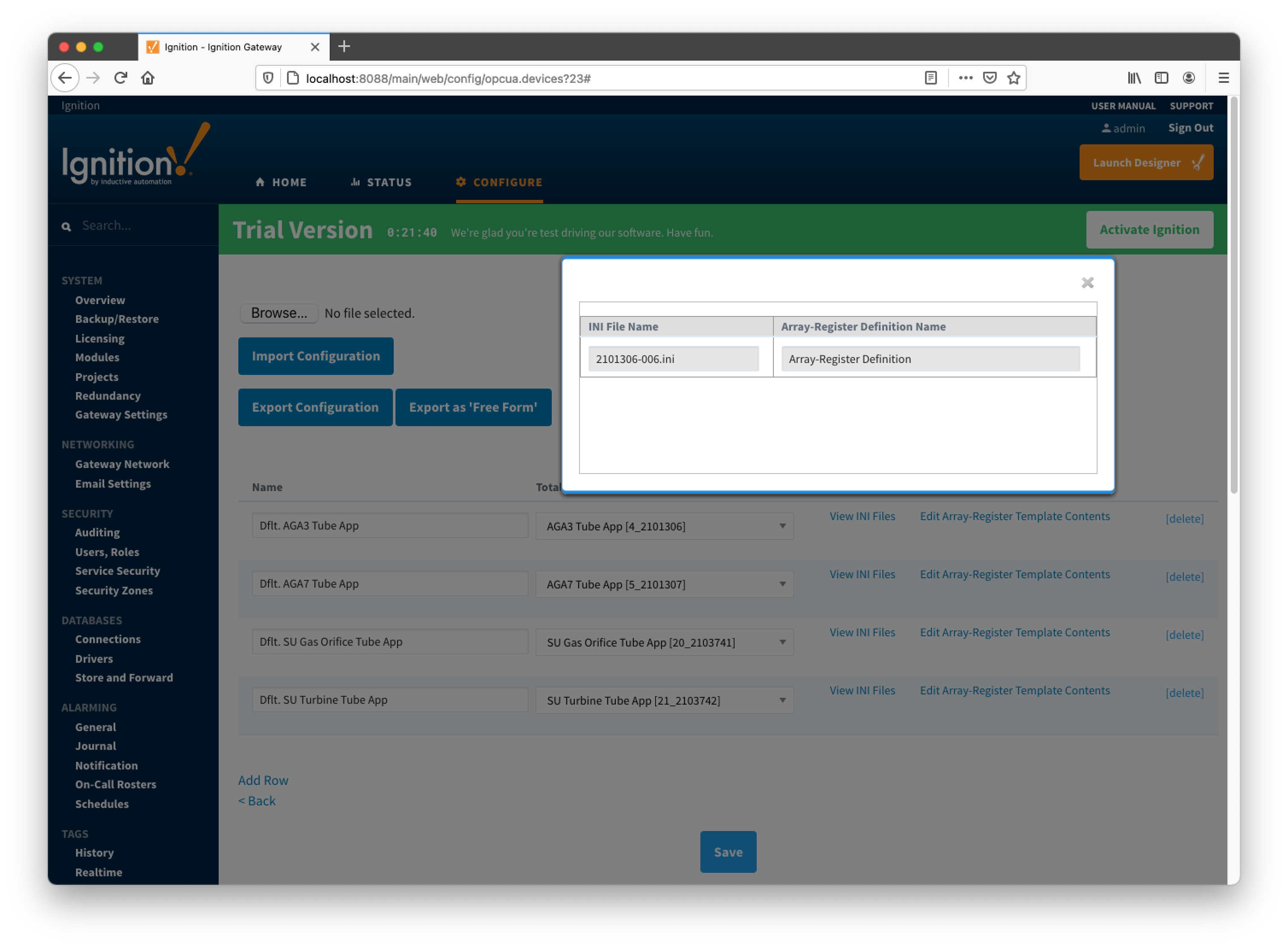
Note that since the revision number for the AGA3-1 meter application is 2101306-006, the INI parser will look for the 2101306-006.ini file in submitted ZIP archive. If no direct match is found, it will look for the another possible match based on the revision number (i.e. 2101306) and revision variant (i.e. 005 and lower). Also note that user has a way to check what INI files were picked by the driver as a source of Array-Register definitions. This information can be obtained form default Array-Register template generated by the driver by following the 'View INI Files' link as shown below:
Below is an example that shows a portion the 2101306-006.ini file for the AGA3 Tube Application:
[Live Analysis Data] ExtHlp 5000 Help 1171 #Columns=2,Description=300,Value=100
dsc:Last Update from THERMS;cmd:4.5.1;typ:S;rwa:1;
dsc:Last Update from Other Source;cmd:4.2.2;typ:D;rwa:1;
dsc:Heating Value Live @ Tb and Pb;cmd:4.3.45;typ:F;
dsc:Real Relative Density Live @ Tb and Pb;cmd:4.3.44;typ:F;
dsc:N2 Live;cmd:4.3.46;typ:F;
dsc:CO2 Live;cmd:4.3.47;typ:F;
dsc:Methane Live;cmd:4.3.51;typ:F;
dsc:H2S Live;cmd:4.3.48;typ:F;
dsc:H2O Live;cmd:4.3.49;typ:F;
dsc:Helium Live;cmd:4.3.50;typ:F;
dsc:Ethane Live;cmd:4.3.52;typ:F;
dsc:Propane Live;cmd:4.3.53;typ:F;
dsc:N-Butane Live;cmd:4.3.54;typ:F;
dsc:I-Butane Live;cmd:4.3.55;typ:F;
dsc:N-Pentane Live;cmd:4.3.56;typ:F;
dsc:I-Pentane Live;cmd:4.3.57;typ:F;
dsc:N-Hexane Live;cmd:4.3.58;typ:F;
dsc:N-Heptane Live;cmd:4.3.59;typ:F;
dsc:N-Octane Live;cmd:4.3.60;typ:F;
dsc:N-Nonane Live;cmd:4.3.61;typ:F;
dsc:N-Decane Live;cmd:4.3.62;typ:F;
dsc:Oxygen Live;cmd:4.3.63;typ:F;
dsc:Carbon Monoxide Live;cmd:4.3.64;typ:F;
dsc:Hydrogen Live;cmd:4.3.65;typ:F;
dsc:Argon Live;cmd:4.3.66;typ:F;
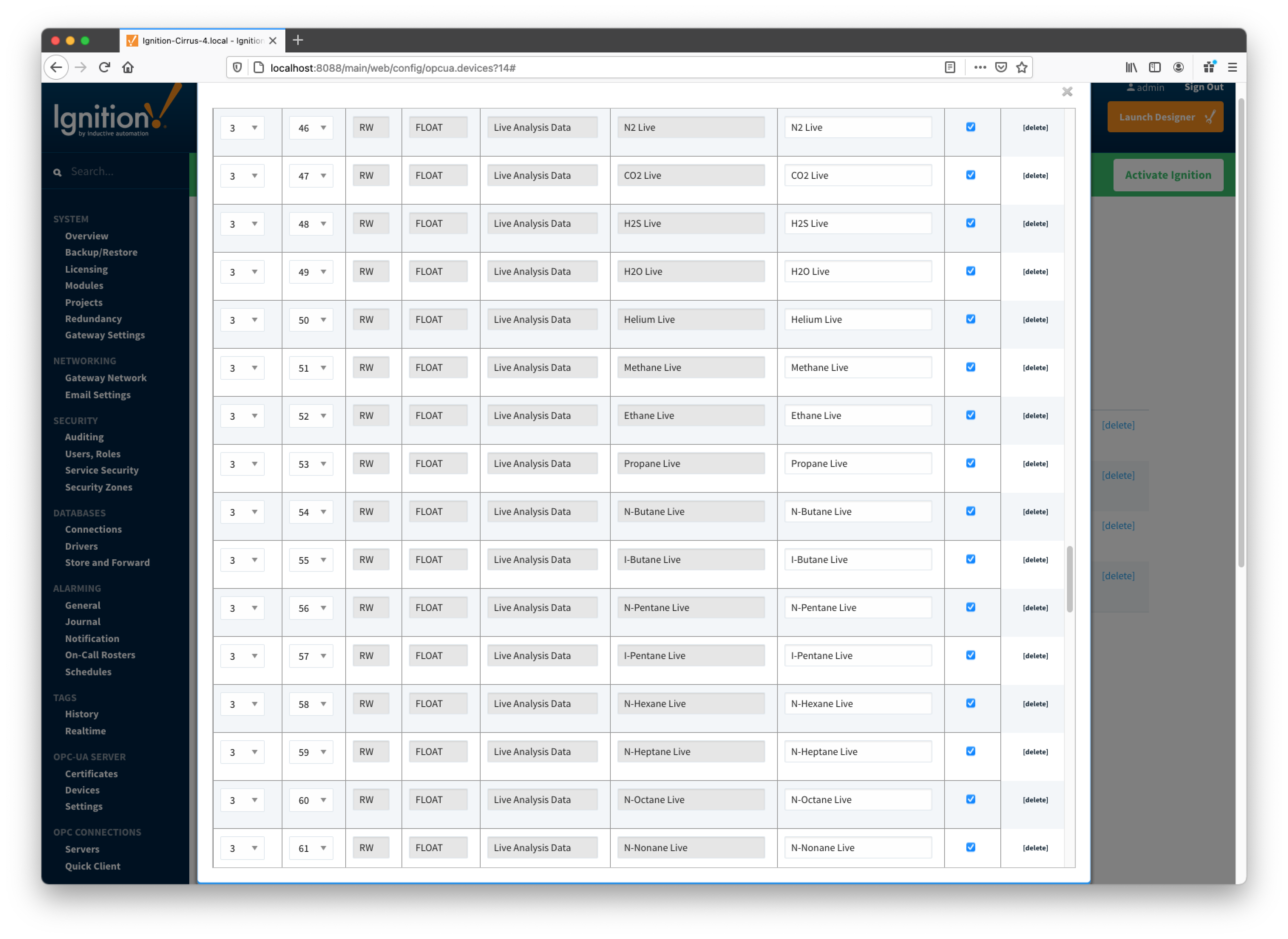
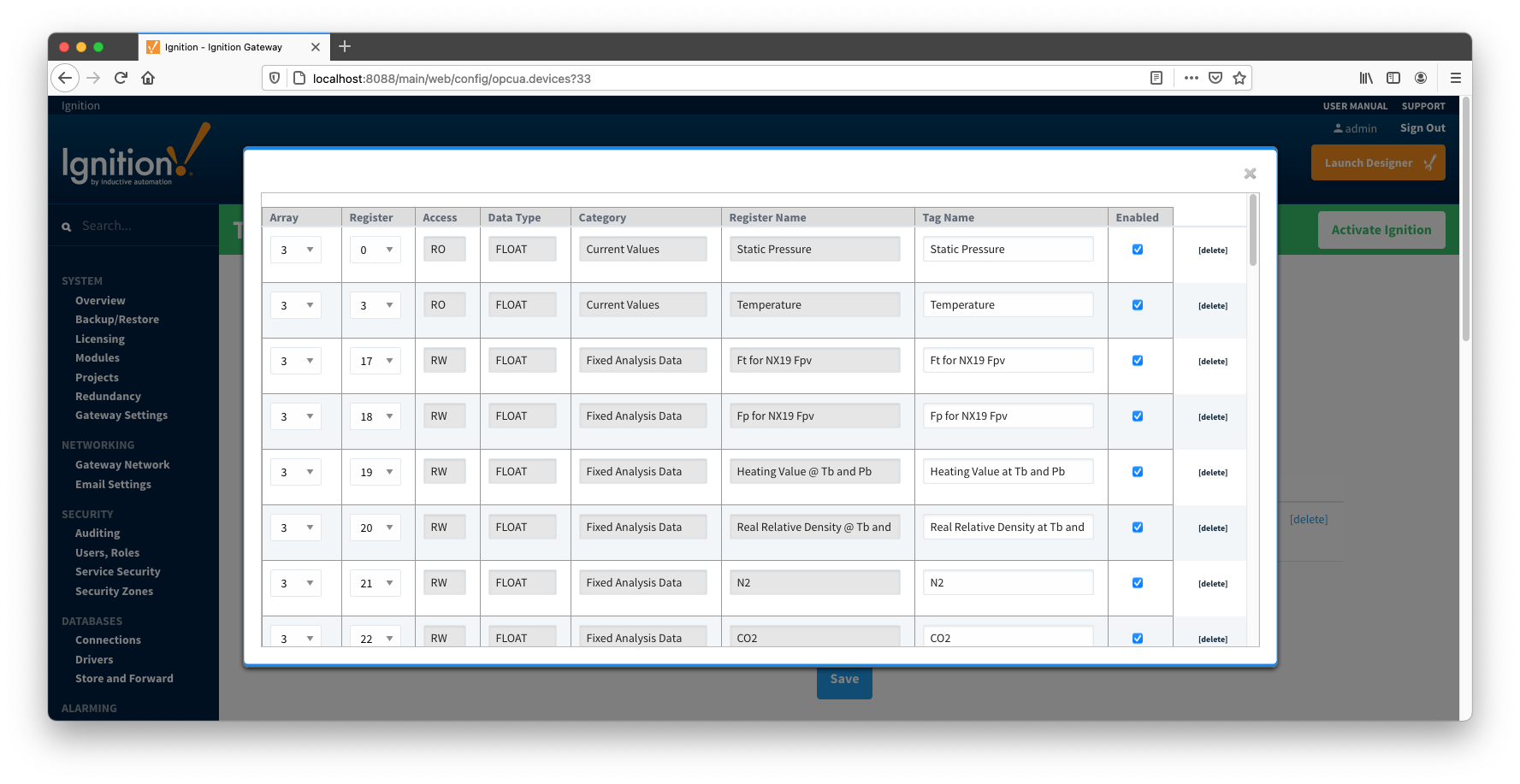
So the driver parses selected INI file and uses the info (i.e. Array-Register definitions) to generate Array-Register templates as shown below. Note how highlighted (bold) lines shown above correlate to Array-Register Templates shown below. Let's look at the 'dsc:N2 Live;cmd:4.3.46;typ:F;' line in more details... The point description (i.e. N2 Live) is being used as a tag name. The 'typ:F' is the data type (i.e. floating point). Finally, the '4.3.46' defines the AAR (i.e. application, array, and register). Note that 4 is not an application slot number, but application enumeration. As a result, a default Array-Register Template is generated by the driver for a specific application enumeration, and it contains all Array-Register points found in appropriate INI files.
Global Totalflow Applications Definitions
An example of the periodic mapping file can be found here: TotalflowApplicationsDefinitions.csv
The Totalflow Applications Definitions tab shows all uploaded application definitions files. This is found via the 'EFM ABB TOTALFLOW' settings on the left 'Config' navigation panel of the Gateway Web UI. It is not part of a specific device connection.
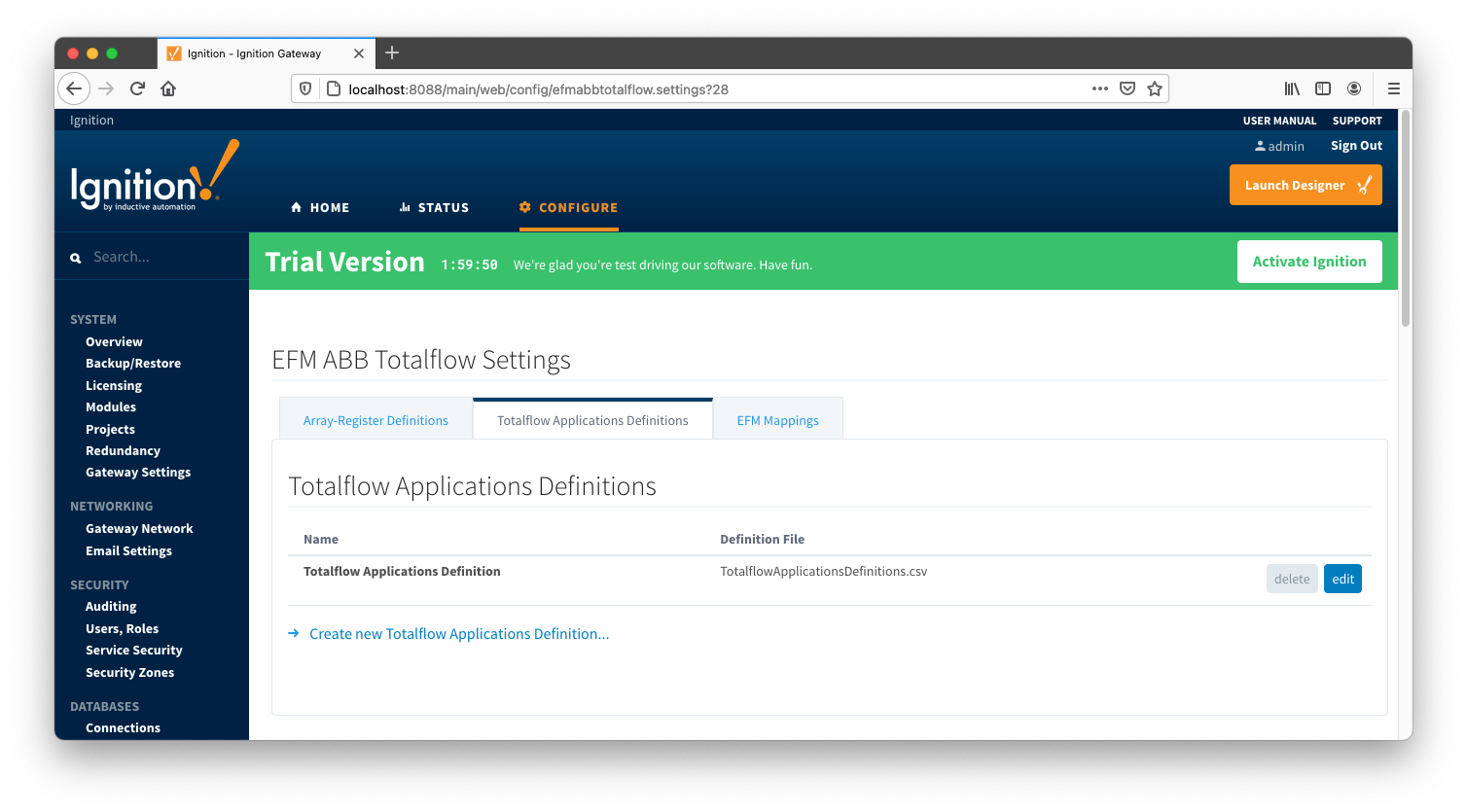
A new Totalflow Applications Definition can be added by clicking on the "Create New Totalflow Applications Definition..." link.
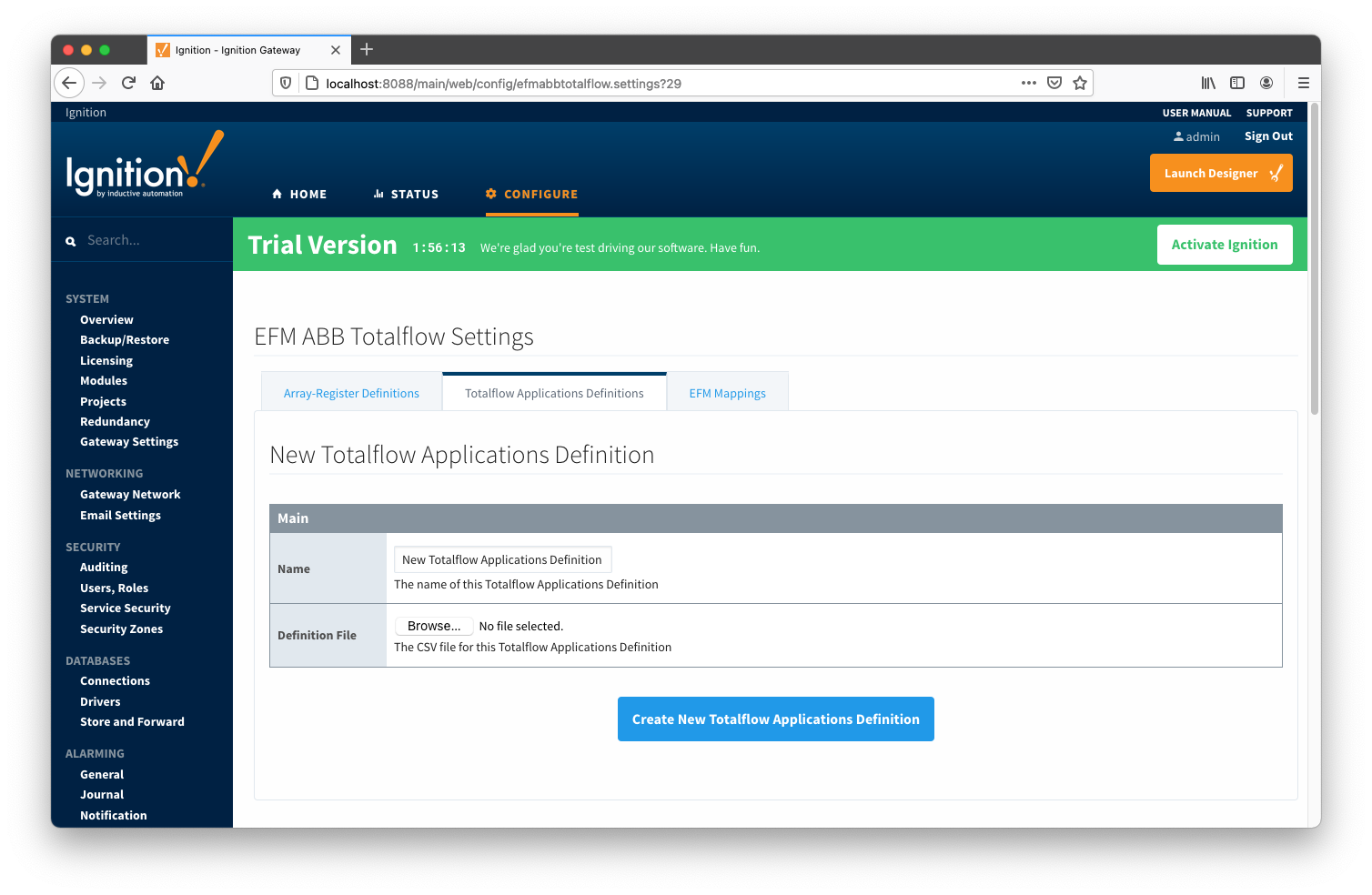
Main Properties
EFM Mappings
The periodic mapping files are used for building up EFM Periodic and Daily History Records. Each row of such file maps specific field of LOG_PERIOD or DAILY records to a database column name. It also allows user to turn a database column off. In other words if column is disabled, respective filed will not be'recordized'. These mappings are CSV files with the following values:
- Array Number
- Array number (i.e. 250 for the LOG_PERIOD_RECORD and 251 for DAILY_RECORD)
- Application Enumeration
- List of application enumerations this mapping entry should be applied. If empty, the mapping entry is applicable to any application.
- Record Field Offset
- Field offset within the record
- Data Type
- Description
- Column Name
- Enabled
- A flag that turns this field 'on/off'. In other words it defines if this field should be recordized.
Below is a mapping example for the LOG_PERIOD_RECORD:
# arrayNum, appEnum, offset, data type, description, column name, enabled
250,4|20,6,FLOAT,Average Differential Pressure,dp_avg,enabled
250,5|21,6,FLOAT,Pulse Counts,pulses,enabled
250,,10,FLOAT,Average Static Pressure,sp_avg,enabled
250,,14,FLOAT,Average Temperature,temp_avg,enabled
250,5|21,18,FLOAT,Uncorrected Volume,raw_vol,enabled
250,,22,FLOAT,Volume,volume,enabled
250,,26,FLOAT,Heating Value,heating_value,enabled
250,,30,UINT16,Flow Time,flo,enabled
250,,32,UINT16,Period Time,flo_rate,enabled
An example of the periodic mapping file can be found here: MeterPeriodicMapping.csv
The Periodic Mappings tab shows all uploaded Periodic Mapping files. This is found via the 'EFM ABB TOTALFLOW' settings on the left 'Config' navigation panel of the Gateway Web UI. It is not part of a specific device connection.
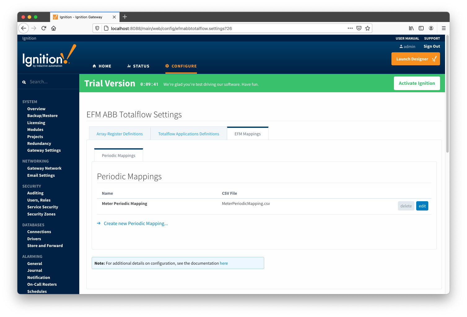
A new Periodic History Mapping can be added by clicking on the "Create New Periodic Mapping..." link.
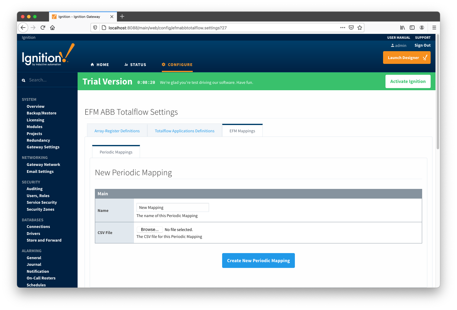
Main Properties
At this point, device connections can be created using global Array-Register definitions submitted earlier.
Creating a Device Connection
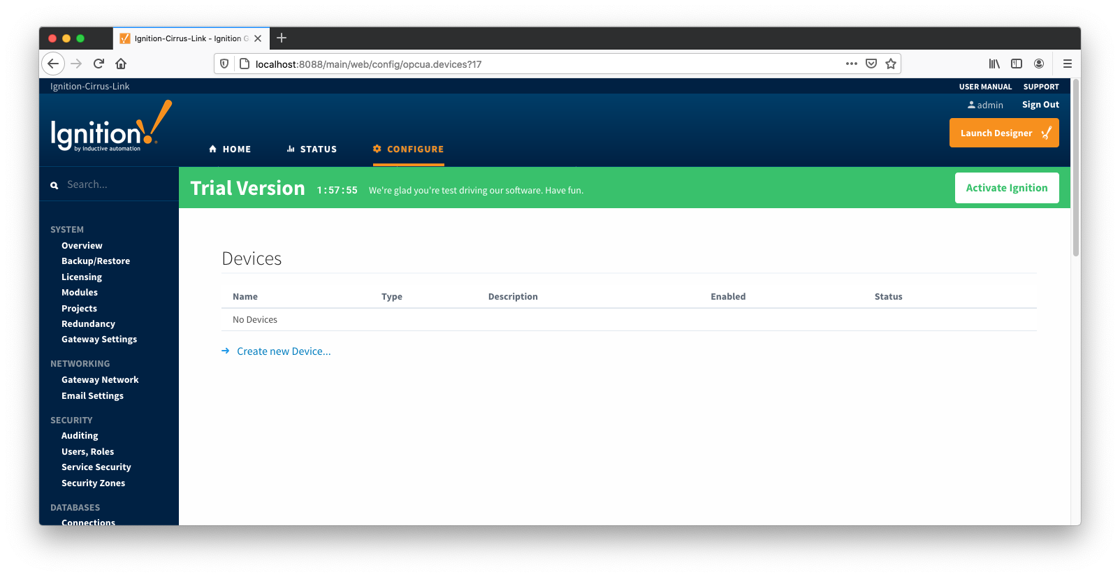
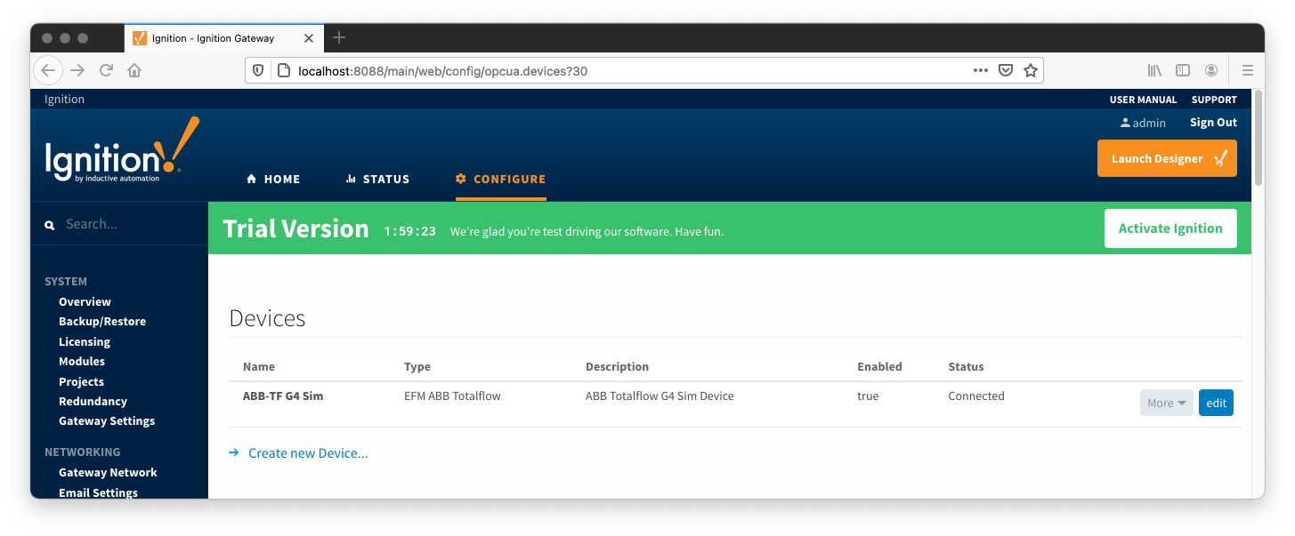
Configuring an ABB Totalflow device connection is done as is with any other driver using the OPC-UA interface. Begin by clicking the Configure tab at the top of the Ignition Gateway web UI and scrolling down to the OPC-UA Server's Devices section and clicking it as shown below.
Once done you will see the following. Click the 'Create new Device...' link to create the ABB Totalflow device connection.
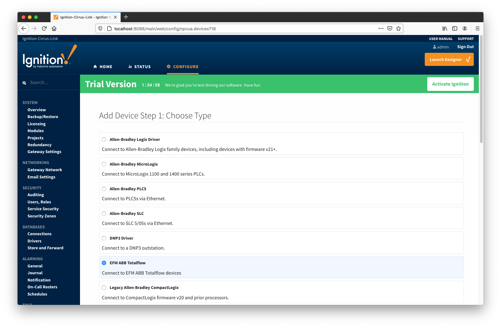
After clicking the 'Create new Device...' link you will see the following. Select the 'EFM ABB Totalflow' and click 'Next' at the bottom of the page.
When creating a new device you will see the following:
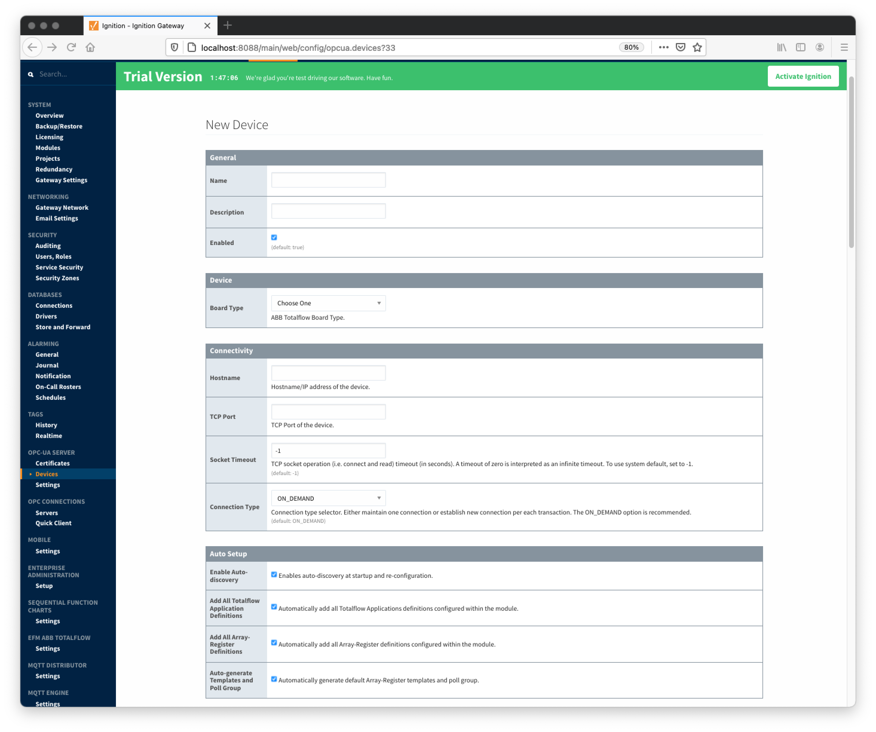
The following describes the parameters that can be set here:
General
Device
- Board Type
- G3 - ABB G3 Flow Computer
- G4 - ABB G4 Flow Computer
- NGC - ABB Natural Gas Chromatograph
Connectivity
- Hostname
- Hostname or IP address of the device
- TCP Port
- Socket Timeout
- TCP socket operation (i.e. connect and read) timeout in seconds. A timeout of zero is interpreted as an infinite timeout. To use system default, set to -1.
- Connection Type
- Connection type selector. Either maintain one connection or establish new connection per each transaction. The ON_DEMAND option is recommended.
- PERSISTENT - The ABB Totalflow driver keeps a TCP connection open and this connection is being shared by all polling threads.
- ON DEMAND - A TCP connection is opened by each polling thread when it needs to poll and closed upon completion. Note that ABB Totalflow device still allows only one connection at a time.
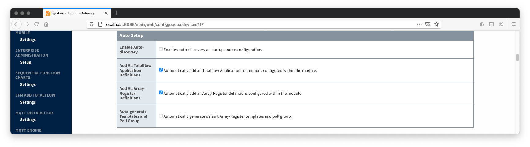
Auto Setup
- Enable auto-discovery
- Enables ABB Totalflow driver to run application auto-discovery at startup and re-configuration.
- Add All Totalflow Application Definitions
- Automatically add all Totalflow Applications definitions configured within the ABB Totoalflow driver module.
- Add All Array-Register Definitions
- Automatically add all the Array-Register definitions configured within the ABB Totoalflow driver module.
- Auto-Generate Templates and Poll Groups
- Automatically generates default Array-Register templates and default poll group on startup and reconfiguration. Note that default Array-Register template will be generated for specific application type (enumeration ) if polling is enabled (see the 'Totalflow Applications Panel' below) for at least one of applications of this type. Another requirement for the default Array-Register template to be generated is that there should not be no any custom template for this application type.
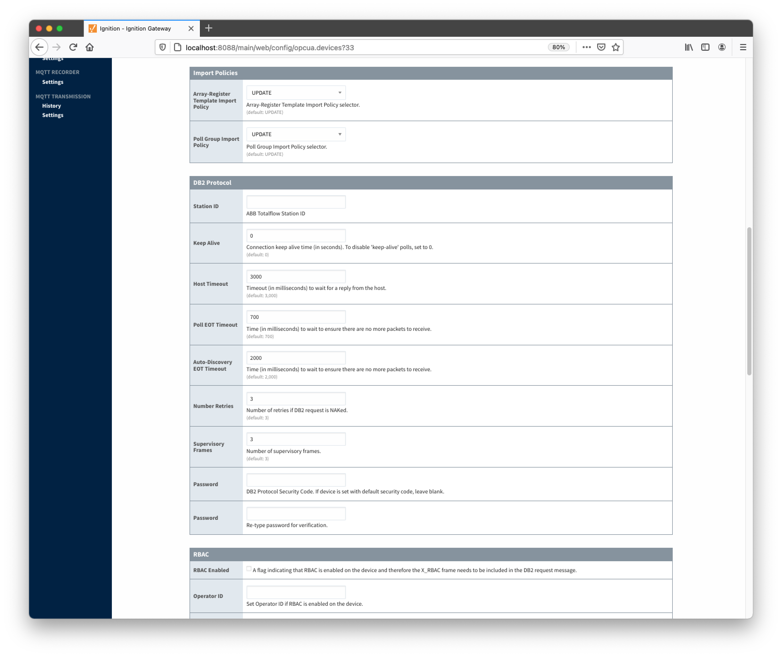
Import Policies
- Array-Register Template Import Policy
- UPDATE - update existing Array-Register Templates
- REPLACE - replace existing Array-Register Templates
- Poll Group Import Policy
- UPDATE - update existing poll groups
- REPLACE - replace existing poll groups
DB2 Protocol
- Station ID
- Station ID of this ABB Totalflow device
- Keep Alive
- Time interval (in seconds) between 'keep-alive' polls that may be required to maintain PERSISTENT connection if ABB Totalflow device is configured to disconnect on inactivity. To disable 'keep-alive' polls, set to 0.
- Host Timeout
- Timeout (in milliseconds) to wait for a reply from the host. The default value is 3000 milliseconds.
- Poll EOT Timeout
- Time (in milliseconds) to wait to ensure there are no more packets to receive. The default value is 700 milliseconds.
- Auto-Discovery EOT timeout
- Time (in milliseconds) to wait to ensure there are no more packets to receive during auto-discovery. The default value is 2000 milliseconds.
- Number Retries
- Number of retries if DB2 request is NAKed.
- Supervisory Frames
- Number of DB2 supervisory frames.
- Password
- DB2 Protocol Security Code. If device is set with default security code of 0000, leave blank.
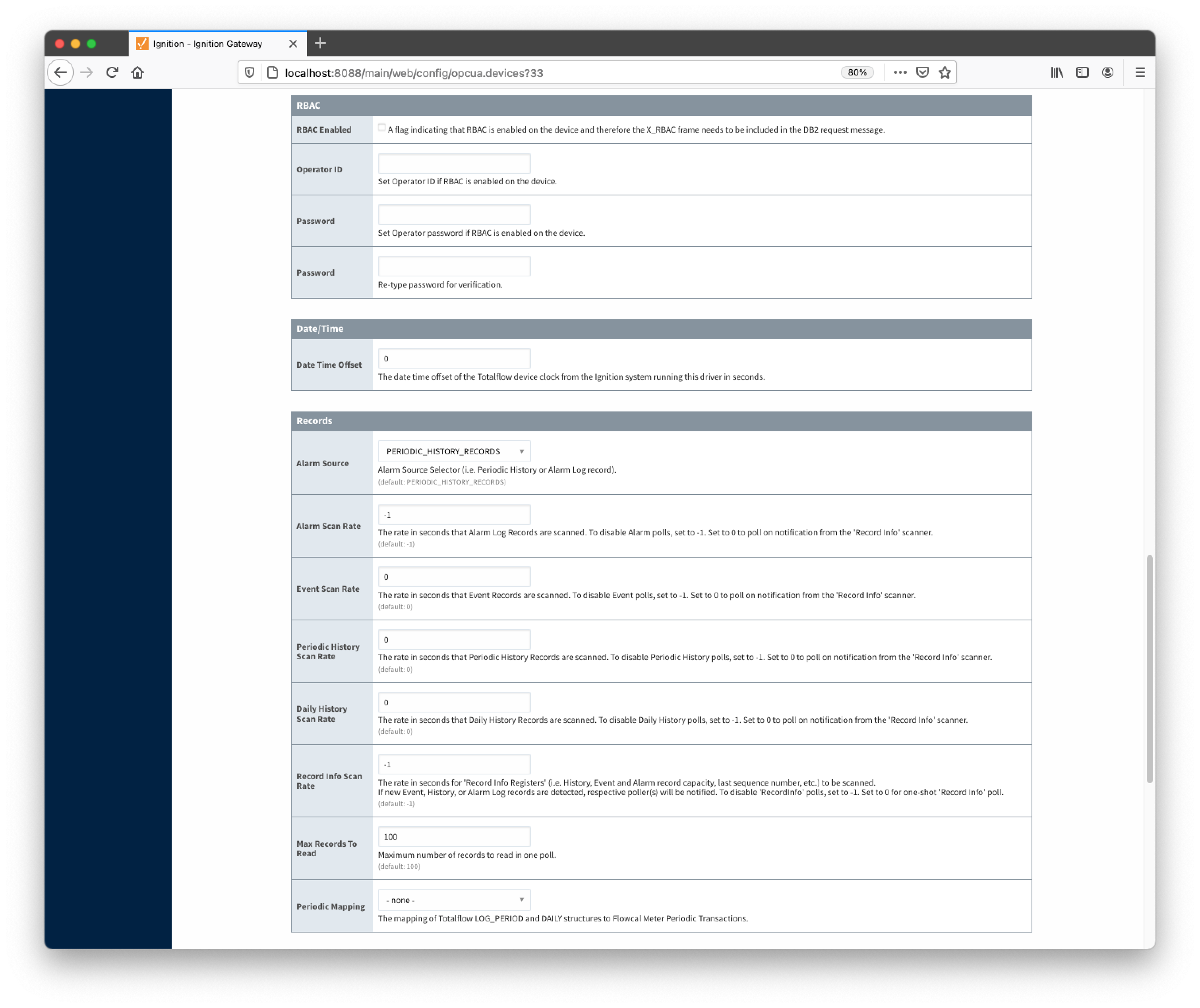
RBAC
- RBAC Enabled
- Enables Role-Based Access Control (RBAC) is enabled on the device and therefore the X_RBAC frame needs to be included in the DB2 request message.
- Operator ID
- Operator ID. If RBAC is not enabled on the device, leave blank.
- Password
- Operator password. If RBAC is enabled on the device, leave blank.
Date/Time
- Date Time Offset
- The date time offset of the Totalflow device clock from the Ignition system running this driver in seconds.
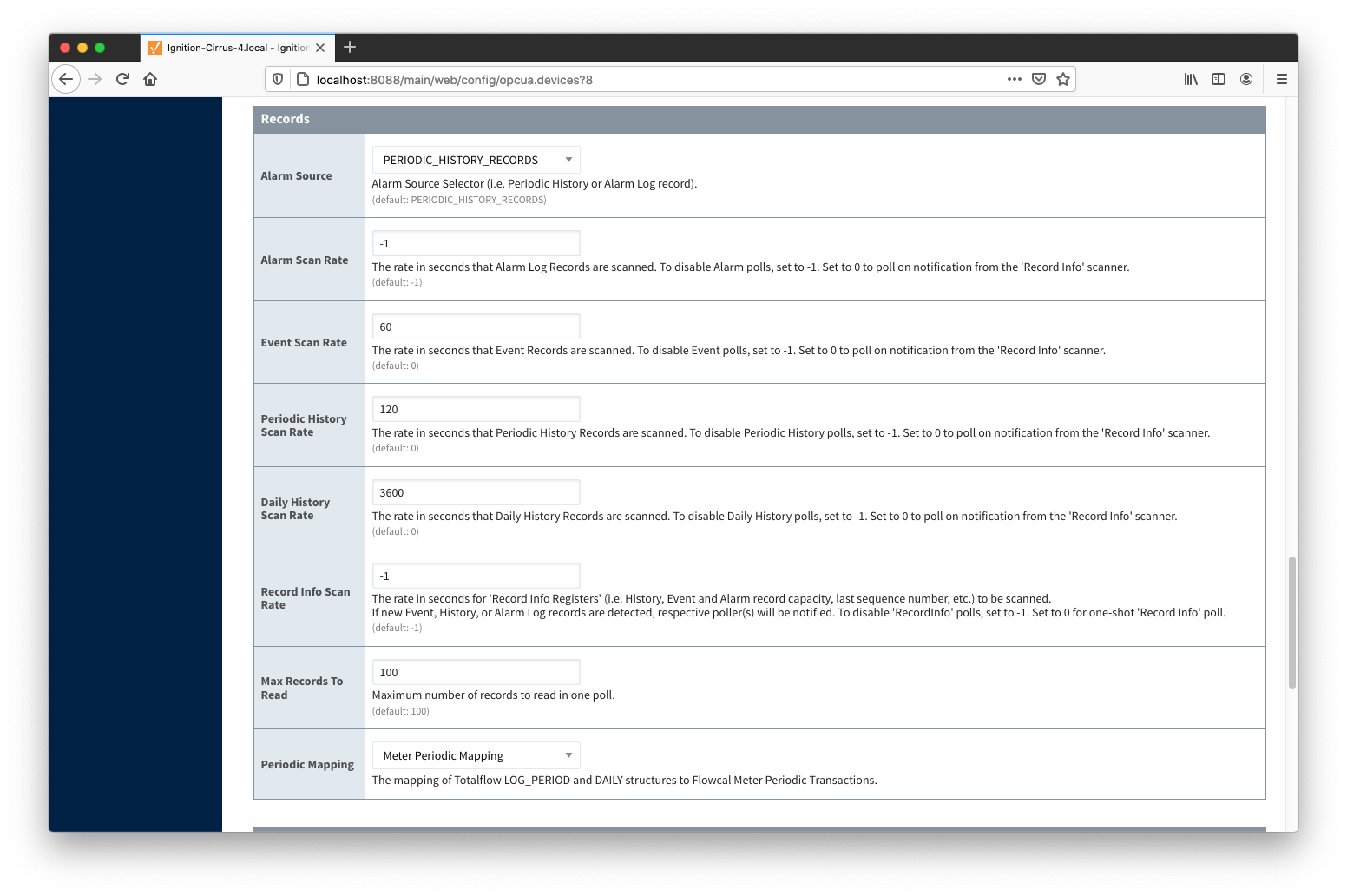
Records
- Alarm Source
Alarm source selector.
- PERIODIC-HISTORY_RECORDS - alarms are obtained from Periodic History records.
- ALARM_LOG_RECORDS - alarms are obtained form Alarm Log records.
- Alarm Scan Rate
- The rate in seconds that Alarm Log Records are scanned. Set to 0 to poll on notification from the 'Record Info' scanner. To disable Alarm polls, set to -1.
- Event Scan Rate
- The rate in seconds that Event Records are scanned. Set to 0 to poll on notification from the 'Record Info' scanner. To disable Event polls, set to -1.
- Periodic History Scan Rate
- The rate in seconds that Periodic History Records are scanned. Set to 0 to poll on notification from the 'Record Info' scanner. To disable Periodic History polls, set to -1.
- Daily History Scan Rate
- The rate in seconds that Daily History Records are scanned. Set to 0 to poll on notification from the 'Record Info' scanner. To disable Daily History polls, set to -1.
- Record Info Scan Rate
- The rate in seconds for the 'Record Info Registers' (i.e. History, Event and Alarm record capacity, last sequence number, etc.) to be scanned.
If new Event, History, or Alarm Log records are detected, respective poller(s) will be notified. To disable 'RecordInfo' polls, set to -1. Set to 0 for one-shot 'Record Info' poll.
- Max. Records to Read
- Maximum number of records to read in one poll.
- Periodic Mapping
- The mapping of Totalflow LOG_PERIOD and DAILY structures to Flowcal Meter Periodic Transactions.
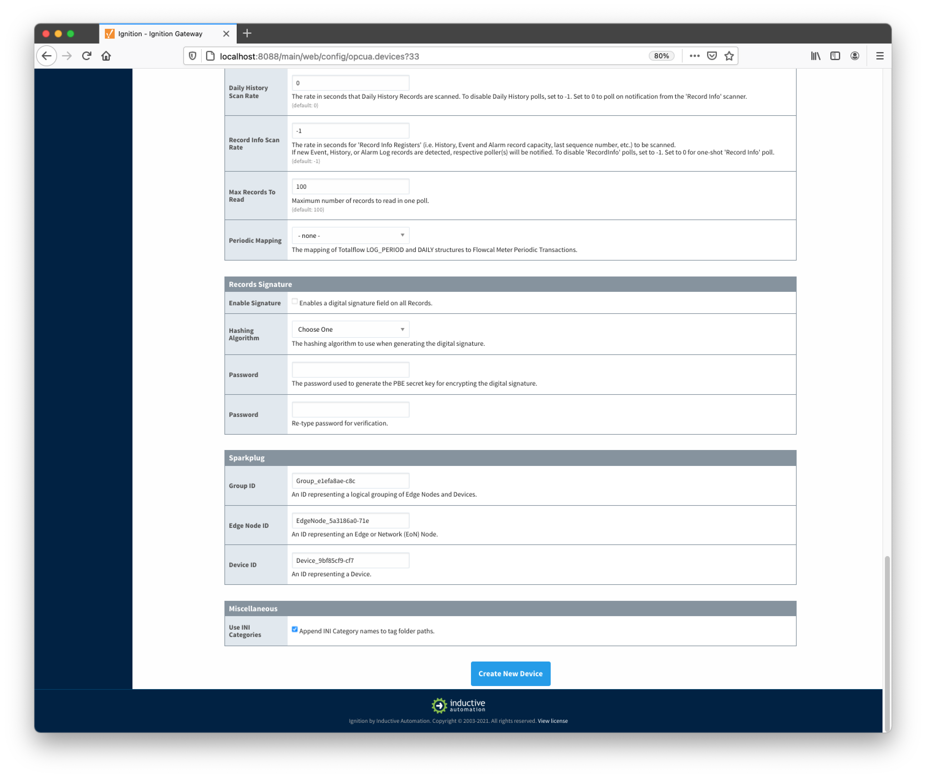
Records Signature
- Enable Signature
- Algorithm
- The hashing algorithm to use when generating the digital signature.
- Password
- The password used to generate the PBE secret key for encrypting the digital signature.
Sparkplug
- Group ID
- An ID representing a logical grouping of Edge Nodes and Devices
- Edge Node ID
- An ID representing an Edge or Network (EoN) Node
- Device ID
- An ID representing a Device
Miscellaneous
- Use INI Categories
- Enables appending INI Category names to tag folder paths
Once the device is created, you should see it is listed in the devices section with a status of either 'Auto-discovery', or 'Connected' on success or "Not Connected" or "Security Failed" on failure.
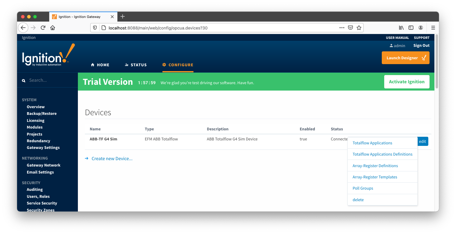
The next sections will show the rest of the configuration that will complete the setup. As a first step, go to the 'Devices' configuration page and click the 'More' button. A drop-down menu with the following five options options will be displayed as shown below:
- Totalflow Applications
- Totalflow Applications Definitions
- Array-Register Definitions
- Array-Register Templates
- Poll Groups
- delete
Configuring Totalflow Applications
The 'Totalflow Applications' configuration panel is populated by the 'auto-discovery' process that takes place on device startup or reconfiguration. Below is an example of what can be displayed on this panel:
At this point, user can enable or disable polling on any listed application and save the changes. Note that polling on all 'Tube' applications is enabled by default.
Specifying Totalflow Applications Definitions for a Device (Optional)
If there are any uploaded global Totalflow applications definition files, they can be applied to this device connection. Do so by clicking the 'More' drop-down button and selecting 'Totalflow Applications Definitions' as shown below:
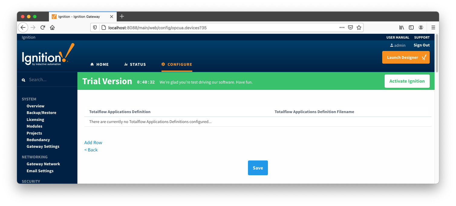
You should now see an empty list of Totalflow applications definitions (unless you used the "Add All Totalflow Applications Definitions" setting). Click the 'Add Row' link that is shown below. This will show a new Totalflow application definition with a select box to allow you to select which global application definition you want to associate with this device. Add as many as are appropriate for your device as shown below:
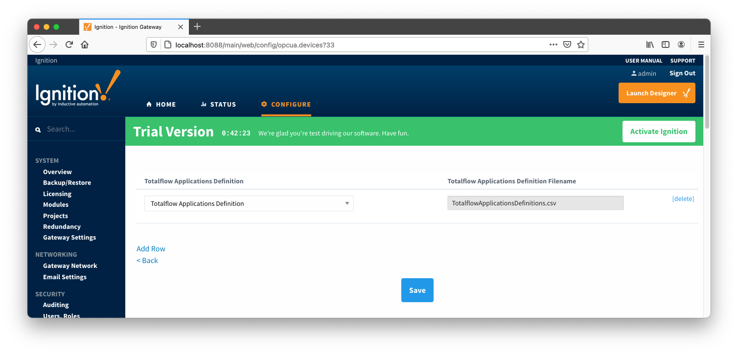
When complete, save the list and you will be taken back to the Devices list.
Specifying Array-Register Definitions for a Device
The next step is to add appropriate global Array-Register definitions to this device connection. Do so by clicking the 'More' drop-down button and selecting 'Array-Register Definitions' as shown below:
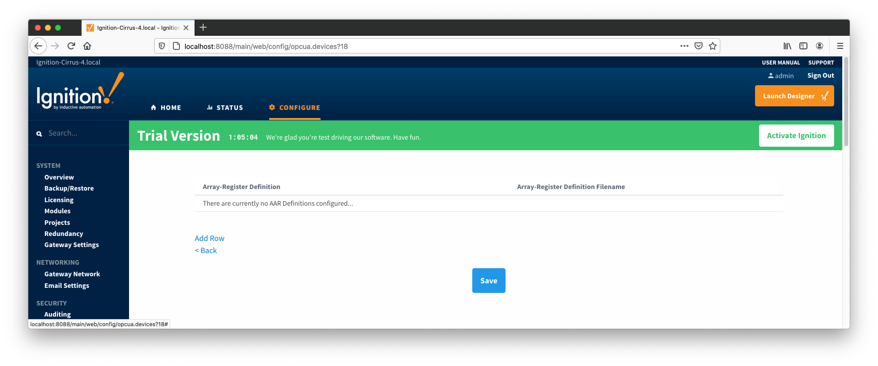
You should now see an empty list of Array-Register definitions (unless you used the "Add All Array-Register Definitions" setting). Click the 'Add Row' link that is shown below. This will show a new Array-Register definition with a select box to allow you to select which global Array-Register definition you want to associate with this device. Add as many as are appropriate for your device as shown below:
When complete, save the list and you will be taken back to the Devices list.
Configuring Array-Register Templates for a Device
With the Array-Register definitions now defined for this device we can create some Array-Register templates to allow creation of Application-Array-Register (AAR) poll groups. Note that the ABB Totalflow driver is capable of generating default Array-Register templates - one per each enabled application type (i.e. application enumeration). If ABB Totalflow device connection was created with the 'Auto-generate Templates and Poll Group' setting turned on, the following default Array-Register templates will be generated for the Totalflow applications shown above:
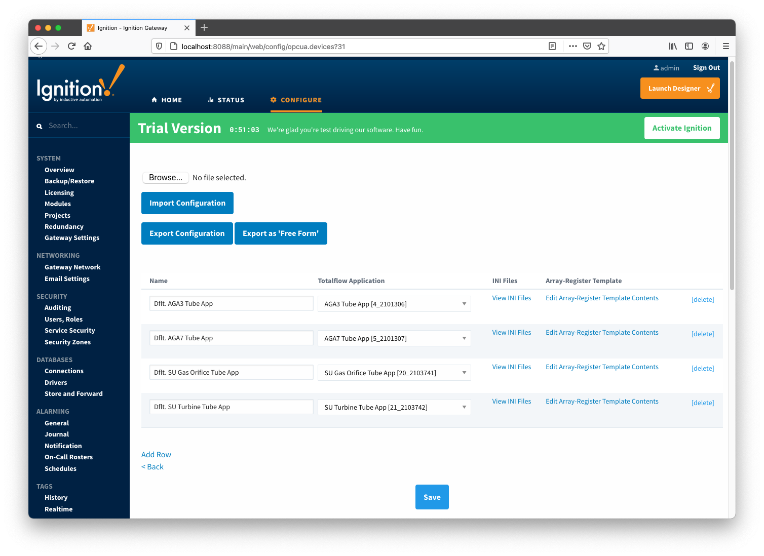
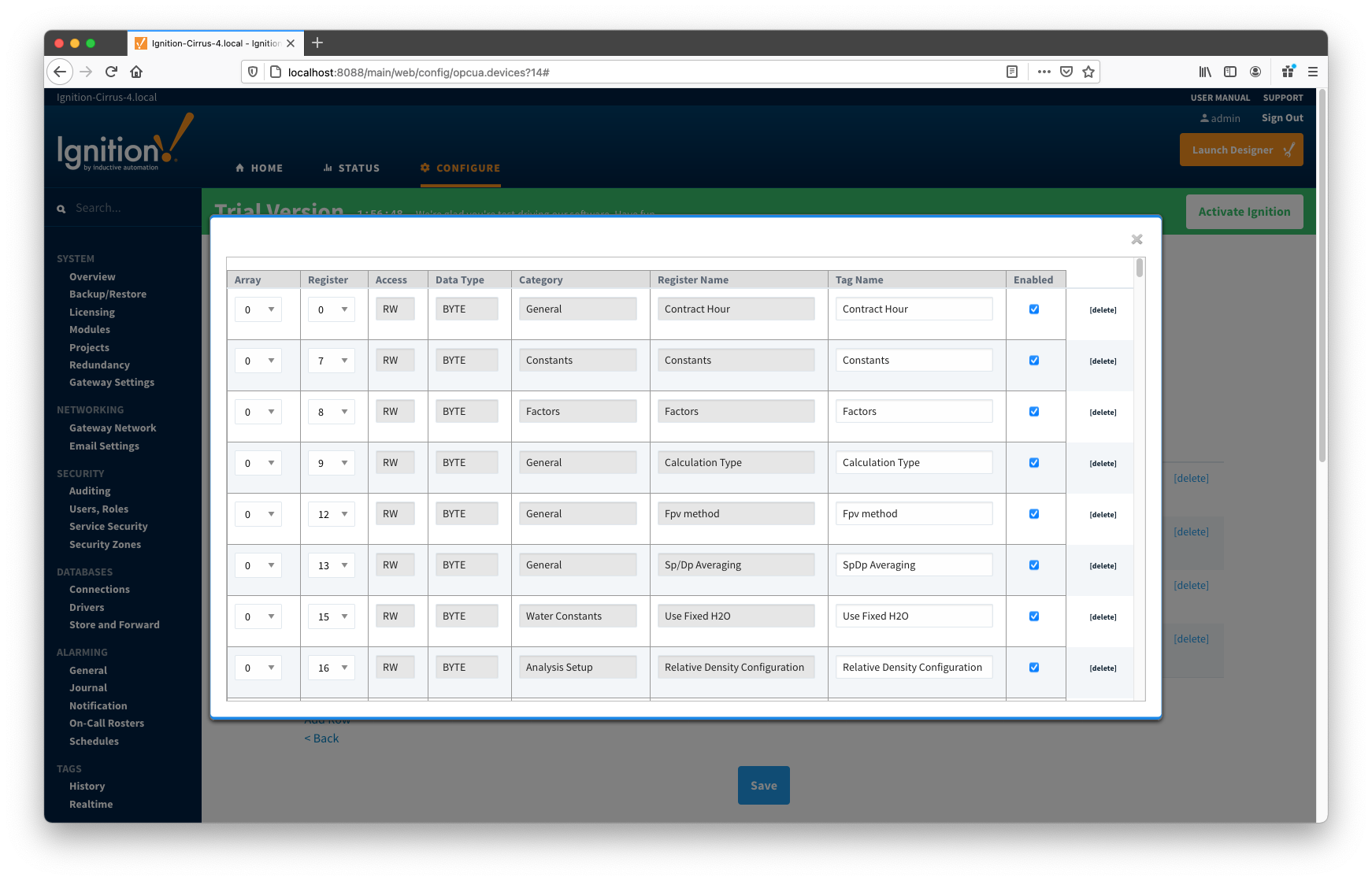
These default templates for each application type will contain all Array-Register points obtained from applied Array-Register definitions that are applicable for this application enumeration. An example of this default template entry page is shown below:
At this point you can do the following:
- Keep things as is.
- This approach will potentially create too many tags that are not really needed.
- Edit default template by either deleting or disabling rows.
- Export default templates as CSV file, edit this file (i.e. remove unwanted data points), and import it back. This approach can result in
- New Array-Register template if original template name was modified in CSV file. In this case original default template will remain untouched.
- Same Array-Register template will have less data points given that template name has not been modified in edited CSV file.
- Delete default Array-Register template and create a new one from scratch. Note that the best practice is to disable the 'Auto-generate Templates and Poll Group' option in device configuration before deleting any templates. Otherwise the driver will attempt to regenerate default template for application enumeration if the following is true:
- The 'Totalflow Application' configuration panel contains at least one application of this type (i.e. enumeration) with polling enabled.
- There is no other custom Array-Register template defined for this application.
Configuring Poll Groups for a Device
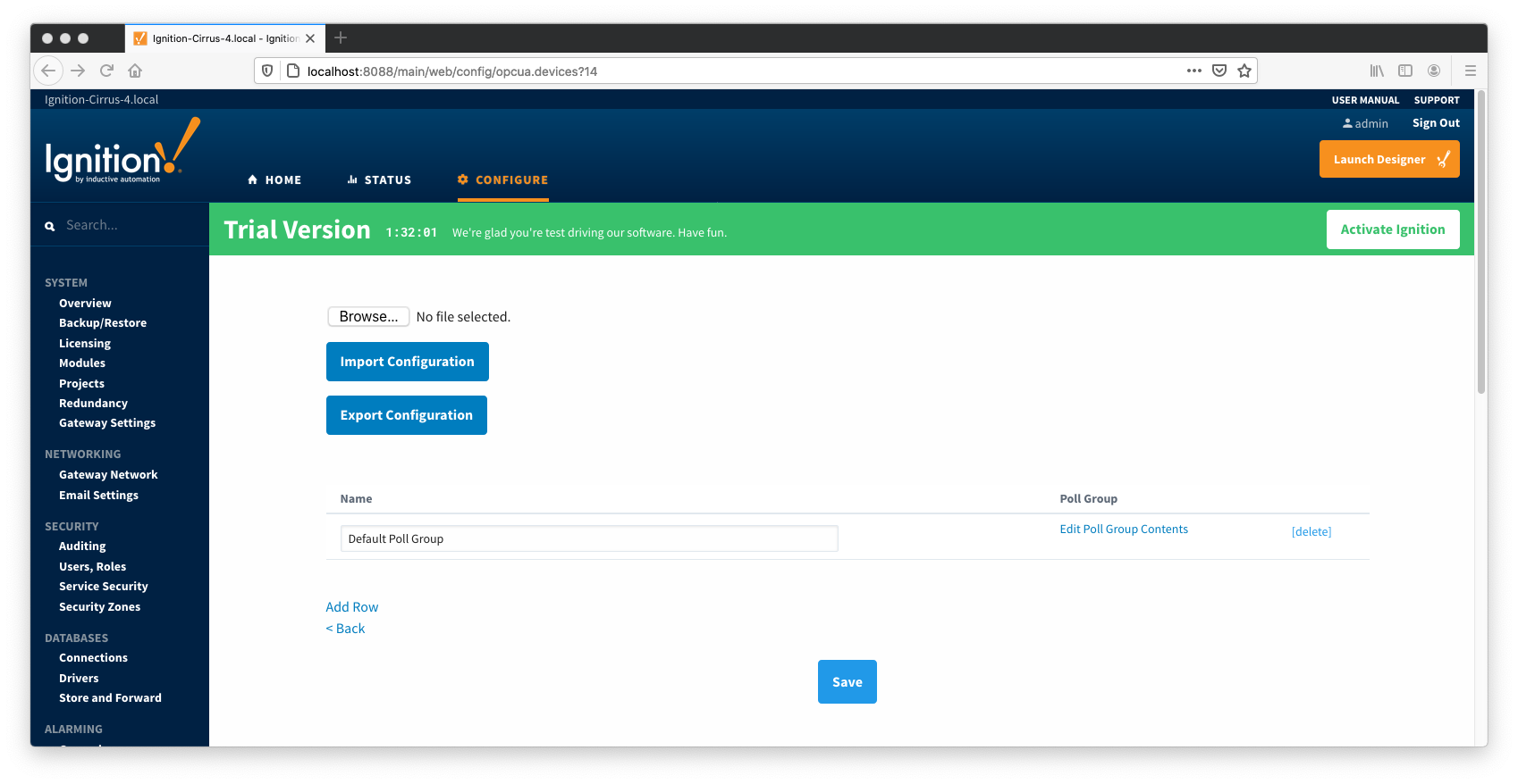
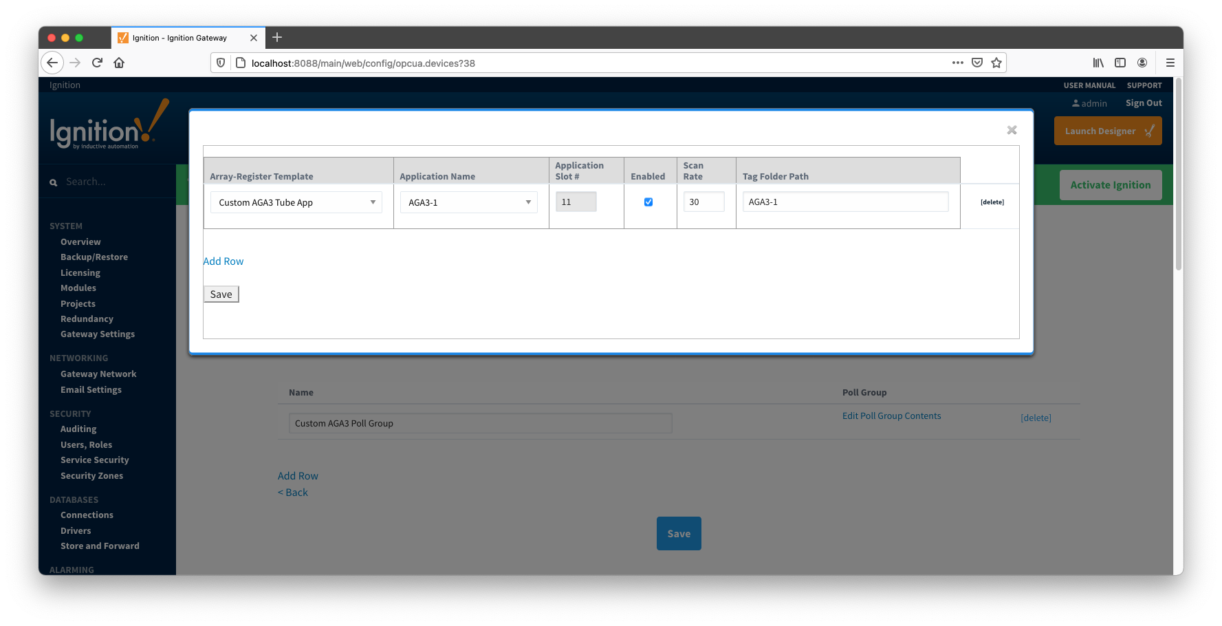
With Array-Register templates already defined, you can now create Application-Array-Register (AAR) poll groups. Note that if ABB Totalflow device connection was created with the 'Auto-generate Templates and Poll Group' setting turned on, the driver will create a default poll group. This default poll group will have one entry per each application enabled on the Totalflow Applications Configuration Panel as shown below:
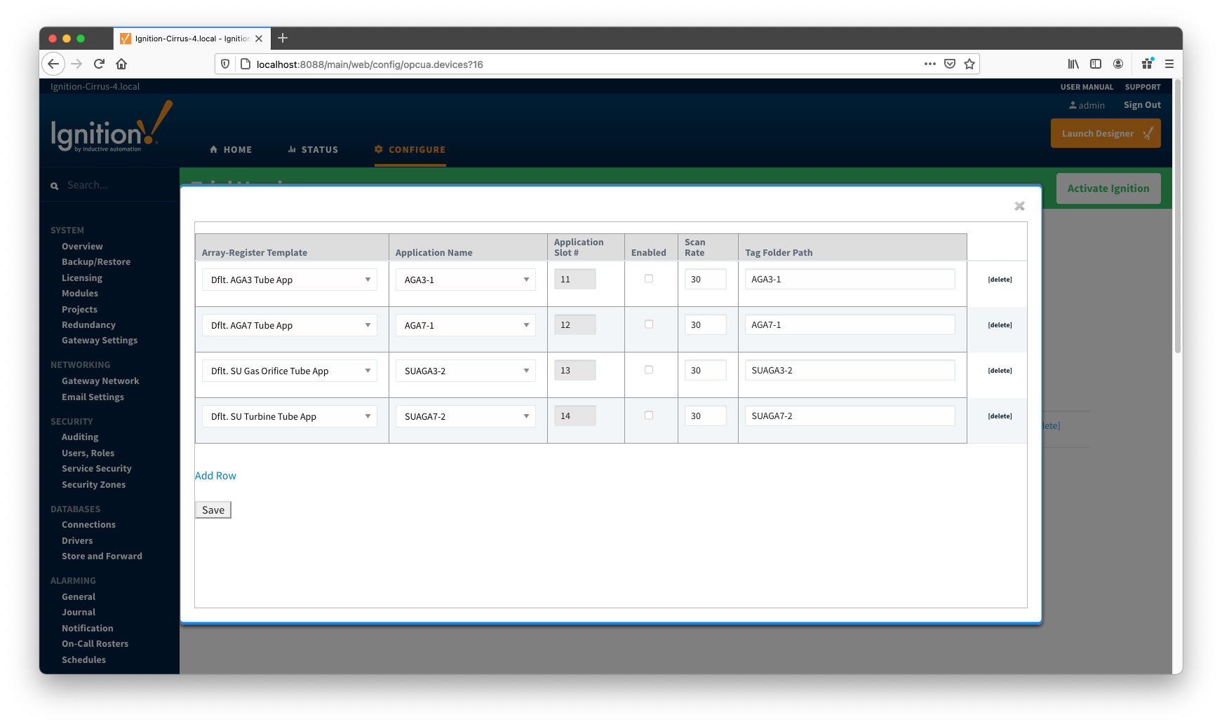
As shown on the picture above, each poll group entry has the following fields:
- Array-Register Template
- This is a select box that allows to point to one of defined Array-Register templates.
- Application Name
- This is a select box that allows to select one of applications enabled on the Totalflow Applications Configuration Panel.
- Application Slot Number
- A slot number for selected Totalflow application
- Enabled
- Allows to enable or disable a polling thread for this polling entry. Note that all default polling entries created are initially disabled and need to be enabled manually.
- Scan Rate
- The scan rate (in seconds) for this polling thread.
- Tag Folder Path
- This is a text box where a tag directory needs to be defined.
When a poll group entry is enabled a polling thread is spawned, and this thread polls for data points defined in the Array-Register template this entry points to. And as with Array-Register templates, if a default poll group entry or entire poll group needs to be deleted, it is the best practice to turn the 'Auto-generate Templates and Poll Group' device configuration option off first.
Viewing Device Application-Array-Register (AAR) Data
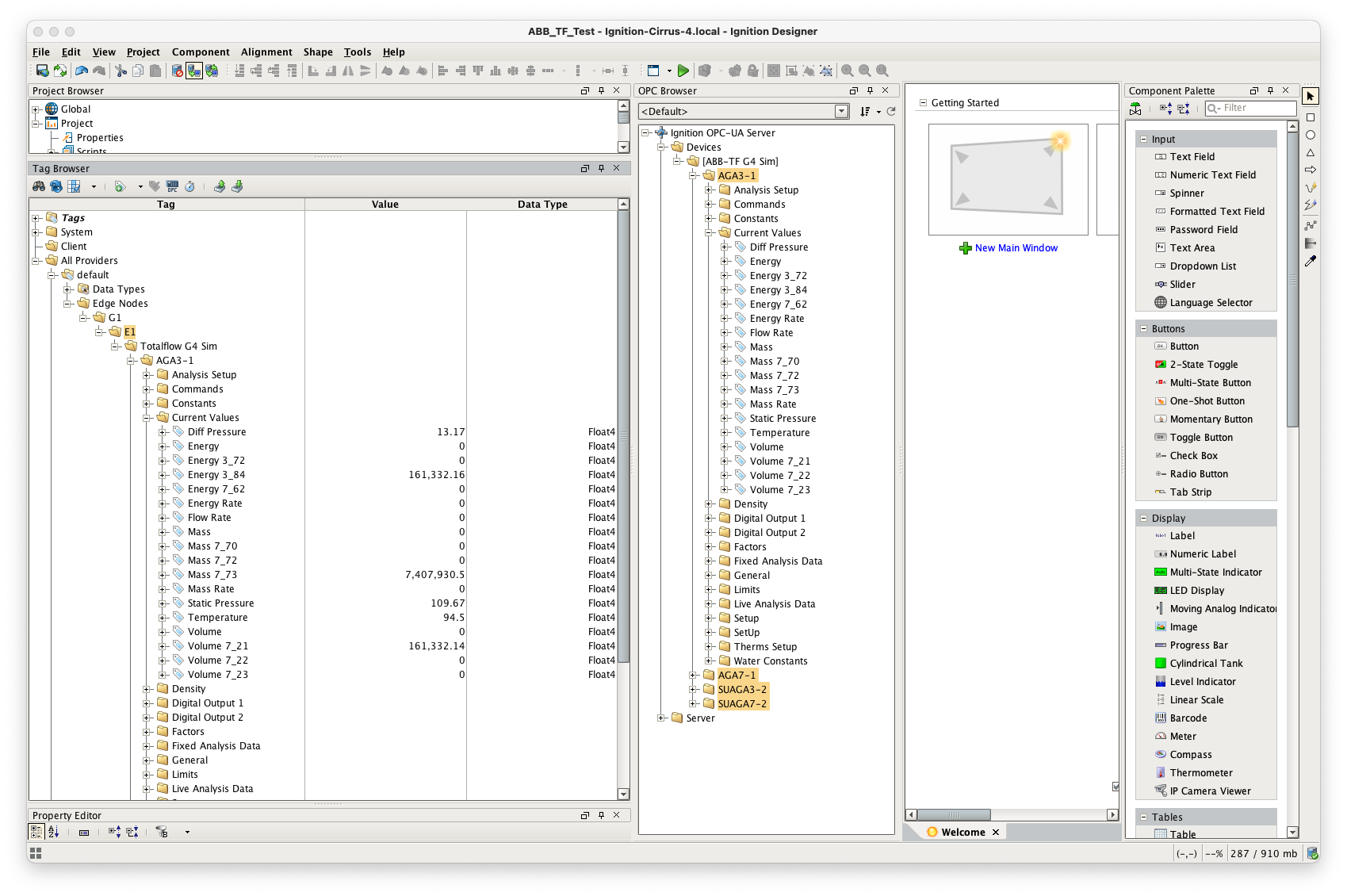
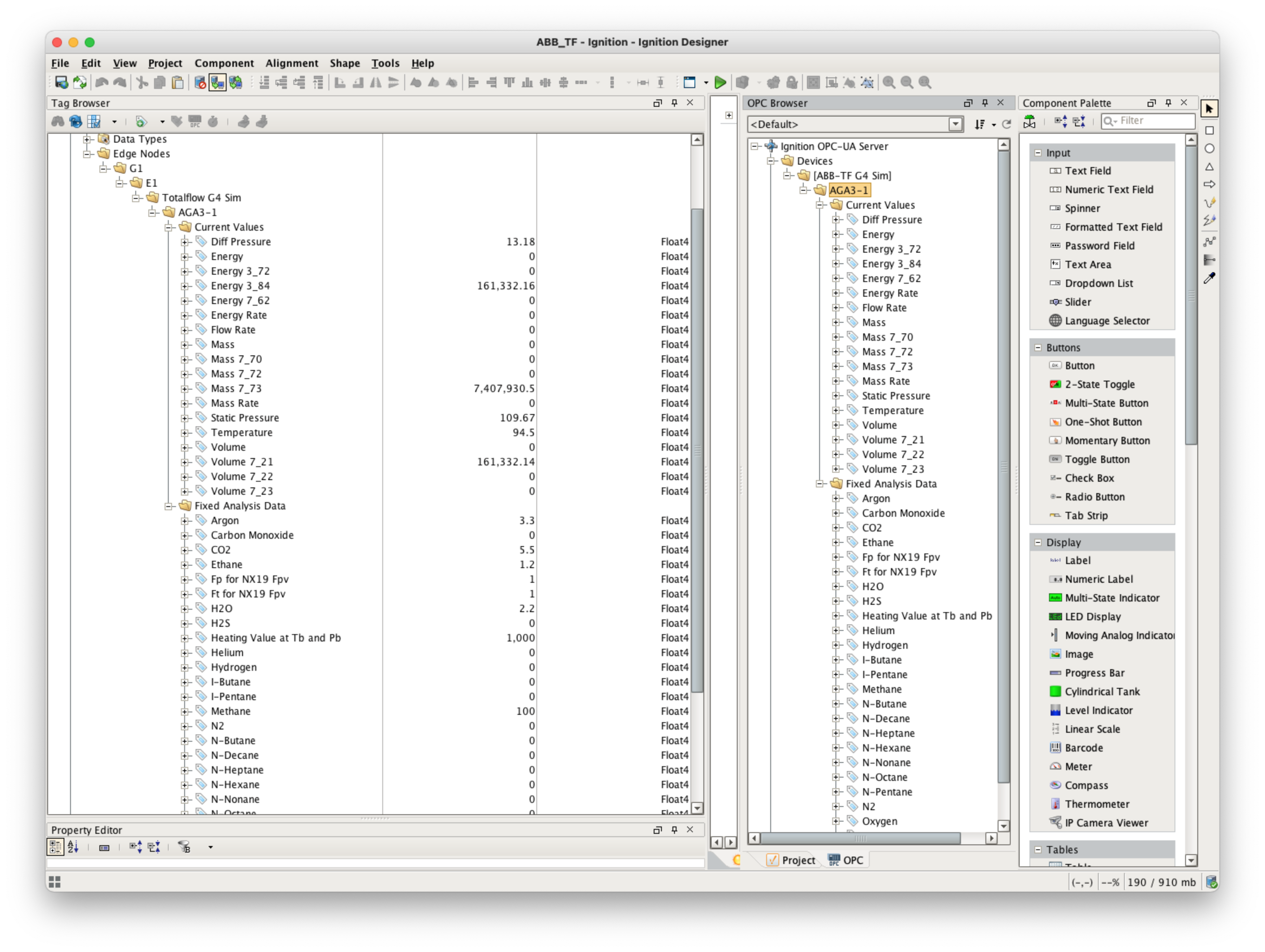
At this point, the ABB Totalflow device should be fully configured. To view data in Ignition launch Ignition Designer and open the OPC Tag Browser as shown below. You should see the tags being polled from the ABB Totalflow device as shown below. You can use these tags as any standard OPC tags in Ignition.
Customizing Array-Register Templates and Poll Groups
The previous sections of this document demonstrated how to:
- Install and set up the EFM ABB Totalflow driver module
- Configure device connection to do the following:
- Connect to the Totalflow device
- Auto-discover applications running on the device
- Generate default Array-Register Templates for all TUBE application enumerations based on information obtained from respective INI file(s)
- Generate default poll group that contains entries for all instantiated TUBE applications
- Poll default poll group
This section will describe how to use default Array-Register templates to generate custom templates and poll groups. For the purpose of this exercise, lets assume that we only want to poll the AGA3-1 application, and we are interested in 'Current Values' and 'Fixed Analysis' data points only. Here is how to do it:
- Go to the 'Auto Setup' section of the device configuration and disable auto-discovery and template auto generation as shown below:
- Go to the 'Poll Group' configuration panel and delete the 'Default Poll Group'
- Go 'Array-Register Templates' configuration panel and delete the following default templates:
- Dflt. AGA7 Tube App
- Dflt. SU Gas Orifice Tube App
- Dflt. SU Turbine Tube App
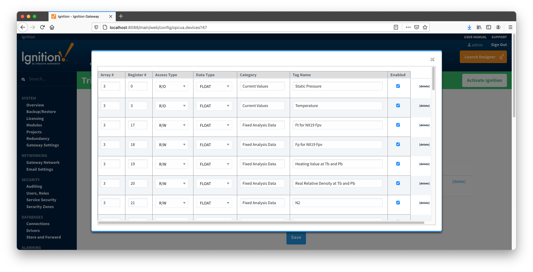
- Click the 'Edit Array-Register Template Contents' link of the 'Dflt. AGA3 Tube App' template
- Edit Array-Register template entries by removing all unwanted entries. In other words, keep an entry only if its category is set to 'Current Values' and 'Fixed Analysis Data'
- Save updated template entries
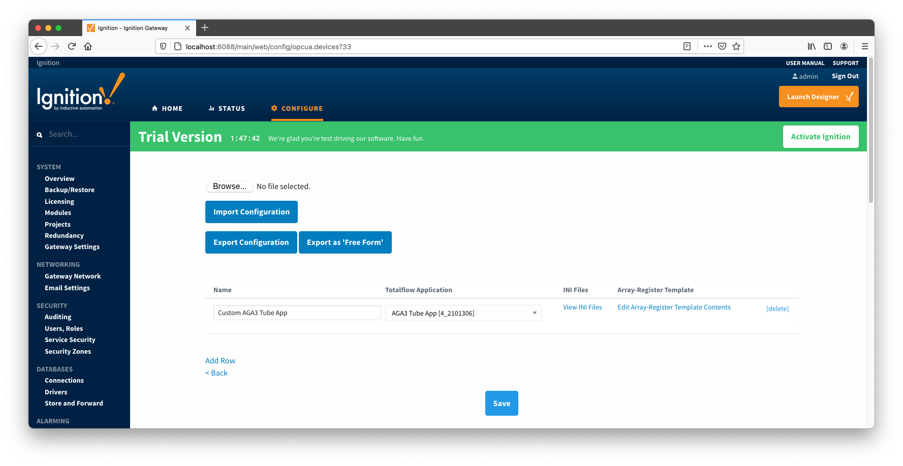
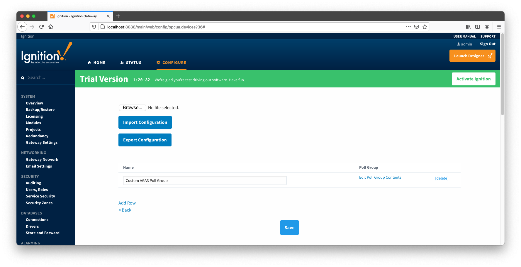
- Rename the 'Dflt. AGA3 Tube App' to 'Custom AGA3 Tube App' and save the template. The 'Array-Register Templates' configuration panel now should look as shown below:
- Go to the 'Poll Group' configuration panel and add a poll group to point to the custom template as shown below:
- Save poll group configuration and the device status should change from 'Connected' to "Polling"
- Open Ignition Designer and view the tags created:
- At this point, custom Array-Register template and poll group cam be exported as CSV files so that they can be reused.
- Note that the 'Array-Register Templates' configuration panel has tow 'export' options:
- Export Configuration - exports Array-Register templates as is
- Export as 'Free Form' templates
- Note that current Array-Register template is INI backed. This means that user can only change the following fields: 'Array', 'Register', 'Tag Name', and 'Enabled'. Other fields such as 'Access', 'Data Type', 'Category', and 'Register Name' are read only and obtained from INI files.
- So if current Array-Register template is exported by clicking the 'Export Configuration' button, it will be exported as INI backed template. The INI-backed_ArrayRegisterTemplates.csv file is an example of such template.
- If current Array-Register template is exported by clicking the Export as 'Free Form' button, it is exported as a 'Free Form' template that can be used without INI file. The Free-Form_ArrayRegisterTemplates.csv file is an example of such template.
- At this point, we can replace an INI backed Array-Register template by the 'Free-Form' one as shown below:
- Go to the device configuration page and change the 'Array-Register Template Import Policy' from 'UPDATE' to 'REPLACE'.
- Import the Free-Form_ArrayRegisterTemplates.csv file and save configuration.
- The Array-Register template should now look like this:

- Note how the 'View INI Files' link is now disabled to reflect that template is not INI backed. Also note that the 'Access', 'Data Type', and 'Category' fields can now be edited.
Viewing Alarm, Event, and Periodic and Daily History data
To view record data which includes ABB Totalflow alarms, events, and history data you must have MQTT Transmission installed on the instance with the EFM ABB Totalflow driver. In addition, the following must be set up.
- Central Gateway
- Install and configure MQTT Engine
- Add/update the Server configuration to point to the MQTT server
- Install MQTT Recorder and configure it to use SQL database connection (previously set up in the Ignition Gateway)
- Edge Gateway
- Install and configure MQTT Transmission
- Add/update the Transmitter configuration and/or the Tag folders so that an Edge Node is reporting with a Group ID, Edge Node ID, and Device ID (for example: G1, E1, D1)
- Add/update the Server configuration to point to the MQTT server
- Click the "Transmission Control/Refresh" Tag to make sure it is connected and reporting.
- Install and configure EFM ABB Totalflow module
- [IMPORTANT] Must have a Sparkplug Group ID, Edge Node ID, and Device ID specified in the device configuration that matches the Edge Node/Device that MQTT Transmission is reporting on
- The Event, and/or History poll rates in the ABB Totalflow driver device configuration must be greater than zero depending on which data you wish to collect. This is shown on the first picture below.
- Another option obtain Events, and/or History data is to set respective poll rates to zero and set the 'Record Info Scan Rate' option to a positive number as shown the second picture below:
- Also note that Alarms can come from two sources:
- PERIODIC_HISTORY_RECORDS
- Alarms are obtained form the Log Period records (Array 250).
- In this case the 'Alarm Scan Rate' should be set to -1.
- ALARM_LOG_RECORDS
- Alarms are obtained form
- Only on meters with the enhanced option turned on.

When all of these conditions are met, alarm, event, and/or history data will be collected, published, and stored via MQTT Recorder in the configured database.
Additional Resources
- Inductive Automation's Ignition download with free trial
- Azure Injector download with free trial
- Questions about this tutorial?
- Sales questions
- About Cirrus Link