Prerequisites
...
- Install IoT Bridge for Snowflake
...
- Before being able to access the
...
- Virtual Machine you must have completed the installation process here.
...
Summary
IoT Bridge for Snowflake (IBSNOW) is an application that connects to an MQTT Server (such as Chariot MQTT Server or AWS IoT Core) and consumes MQTT Sparkplug messages from Edge devices. These messages must be formatted as Sparkplug Templates. Sparkplug Templates are defined in the Sparkplug Specification. These Templates are used to create the data in Snowflake automatically with no additional coding or configuration. Then multiple instances of these Templates generate the Assets and start to populate with real time data sent on change only, thus significantly reducing the amount of data being sent to the cloud. For further details on Snowflake, refer to the documentation here. For further details on Eclipse Sparkplug, refer to the Eclipse Sparkplug resources.
This Quickstart document covers how IoT Bridge can be used to consume MQTT Sparkplug data and create and update data in Snowflake. This will show how to configure IoT Bridge as well as show how to use Inductive Automation's Ignition platform along with Cirrus Link's MQTT modules to publish device data to an MQTT Server. This data will ultimately be consumed by IoT Bridge to create and update the Snowflake components. This tutorial will use the AWS IoT Core MQTT Server implementation. However, IBSNOW does work with any MQTT v3.1.1 compliant MQTT Server.
It is also important to note that Ignition in conjunction with Cirrus Link's MQTT Transmission module converts Ignition User Defined Types (UDTs) to Sparkplug Templates. This is done automatically by the MQTT Transmission module. So, much of this document will refer to UDTs rather than Sparkplug Templates since that is what they are in Ignition. More information on Inductive Automation's Ignition platform can be found here. Additional information on Cirrus Link's MQTT Transmission module can be found here.
AWS Setup
Before configuring IoT Bridge (IBSNOW), you must register a 'thing' connection in AWS IoT Core. Begin by browsing to AWS IoT Core in your AWS account. Make sure you are in the same AWS region that you have already deployed IBSNOW to. Begin by expanding 'Secure' and click 'Policies' as shown below.
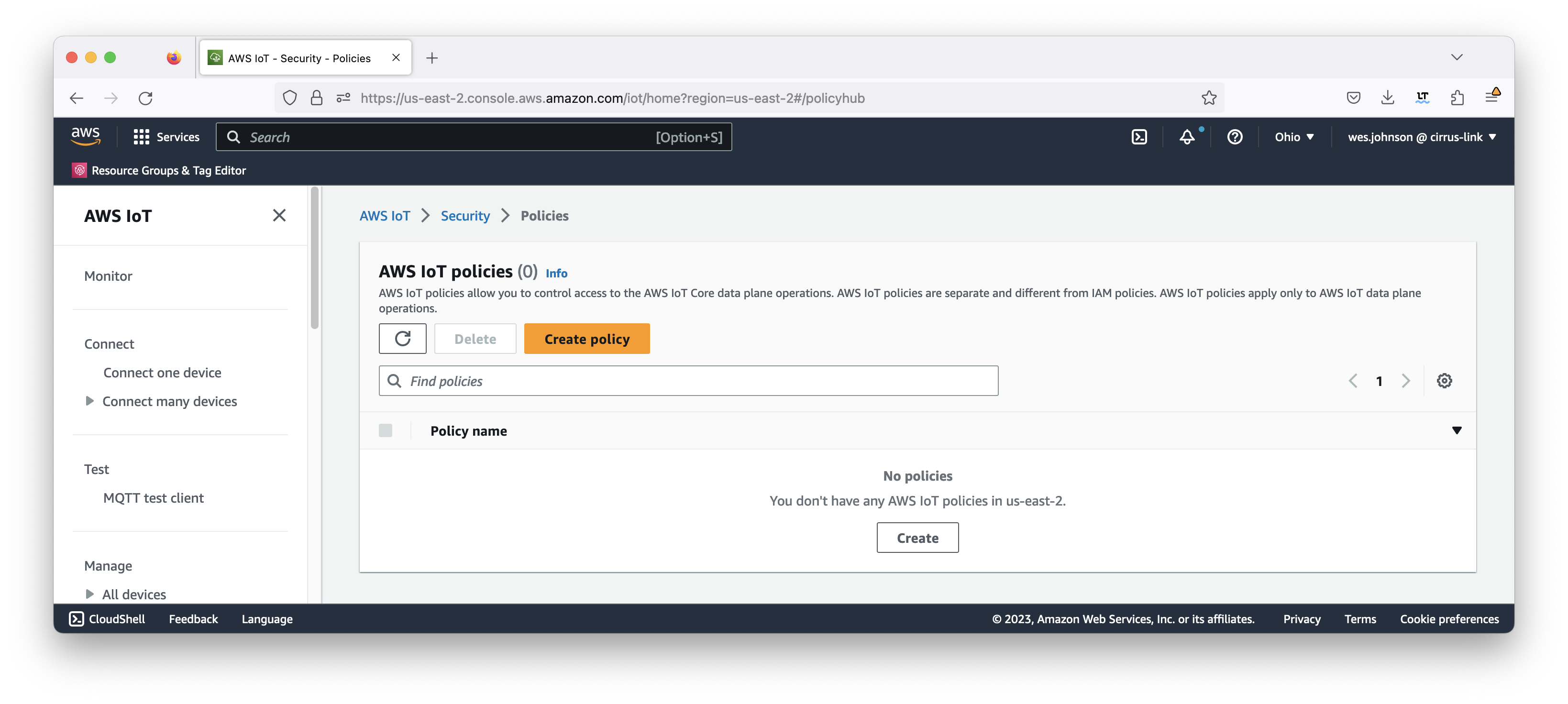 Image Removed
Now click the 'Create a policy' button. This will bring up the following page.
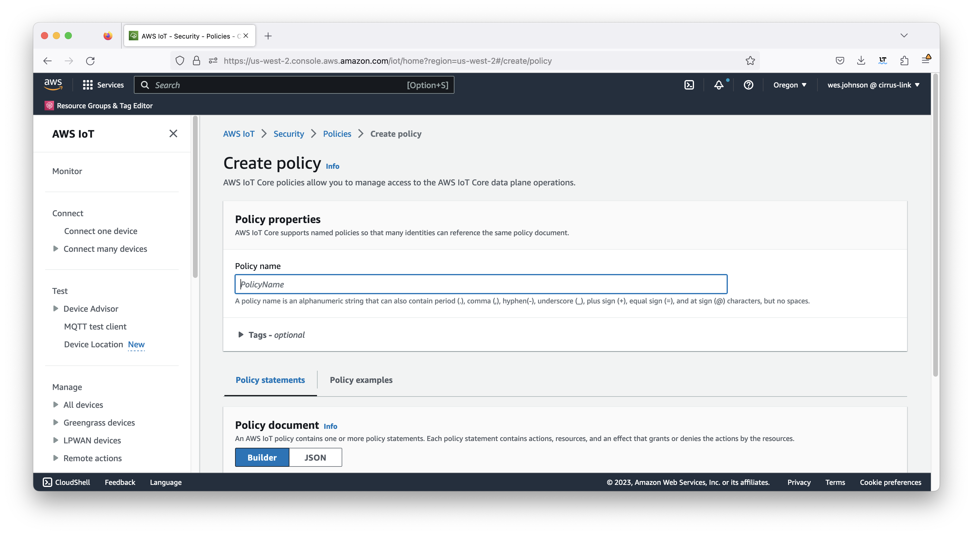 Image Removed
Set the following parameters for the policy.
...
- Some friendly name you will remember
...
Set to the following JSON document but replace the following
...
ACCOUNT_ID: Your AWS Account ID
| Code Block |
|---|
{
  "Version": "2012-10-17",
  "Statement": [
    {
      "Effect": "Allow",
      "Action": [
        "iot:Connect",
        "iot:Publish",
        "iot:Subscribe",
        "iot:Receive",
        "iot:RetainPublish"
      ],
      "Resource": "arn:aws:iot:AWS_REGION:ACCOUNT_ID:*"
    }
  ]
} |
Install an MQTT Server configured with a real signed TLS certificate
| Tip |
|---|
This quickstart guide uses the Chariot MQTT Server can be installed as a free trial from the AWS Marketplace. Review the Chariot MQTT Server Configuration for details on how to upload the necessary certificates and keys for enabling SSL/TLS |
| Note |
|---|
If you choose not to use Chariot MQTT Server, any Sparkplug compliant MQTT Server will work. | Warning |
|---|
| AWS IoT Core has a message size limit of 128KB and will disconnect the client if it receives a message that exceeds this limit. If you have a large number of UDT definitions/instances and/or have very large UDTs, you will very likely hit this limit when sending your UDTs to AWS IoT Core. Review this document for ways to reduce the message size. |
|
Summary
IoT Bridge for Snowflake (IBSNOW) is an application that connects to an MQTT Server (such as Chariot MQTT Server or AWS IoT Core) and consumes MQTT Sparkplug messages from Edge devices.
When these messages are formatted as Sparkplug Templates, as defined in the Sparkplug Specification, the templates are used to create the data in Snowflake automatically with no additional coding or configuration.
| Warning |
|---|
| If the messages do not use templates, they will be stored in a database table as unprocessed messages and additional work will be required to use this data in Snowflake. |
Then multiple instances of these Templates generate the Assets and start to populate with real time data sent on change only, thus significantly reducing the amount of data being sent to the cloud. For further details on Snowflake, refer to the documentation here. For further details on Eclipse Sparkplug, refer to the Eclipse Sparkplug resources.
This Quickstart document covers how IoT Bridge can be used to consume MQTT Sparkplug data and create and update data in Snowflake. This will show how to configure IoT Bridge as well as show how to use Inductive Automation's Ignition platform along with Cirrus Link's MQTT modules to publish device data to an MQTT Server. This data will ultimately be consumed by IoT Bridge to create and update the Snowflake components. This tutorial will use the AWS IoT Core MQTT Server implementation. However, IBSNOW does work with any MQTT v3.1.1 compliant MQTT Server including Cirrus Link's MQTT Servers.
It is also important to note that Ignition in conjunction with Cirrus Link's MQTT Transmission module converts Ignition User Defined Types (UDTs) to Sparkplug Templates. This is done automatically by the MQTT Transmission module. So, much of this document will refer to UDTs rather than Sparkplug Templates since that is what they are in Ignition. More information on Inductive Automation's Ignition platform can be found here. Additional information on Cirrus Link's MQTT Transmission module can be found here.
Snowflake Setup
If you don't have a Snowflake account, open a Web Browser and go to https://www.snowflake.com. Follow the instructions there to start a free trial. After creating an account, log in to Snowflake via the Web Console. You should see something like what is shown below.
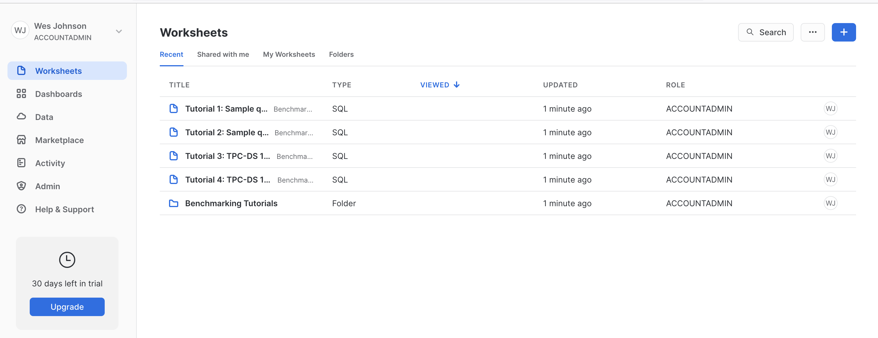 Image Added
Create a new 'SQL Worksheet' by clicking the blue + button in the upper right hand corner of the window as shown below.
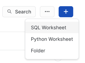 Image Added
Copy and paste SQL Script 01 from Snowflake Setup Scripts into the center pane of the SQL Worksheet, click the drop down arrow next to the blue play button in the upper right corner of the window and click 'Run All' as shown below.
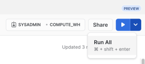 Image Added
After doing so, you should see a message in the 'Results' pane denoting the SPARKPLUG_RAW table was created successfully as shown below.
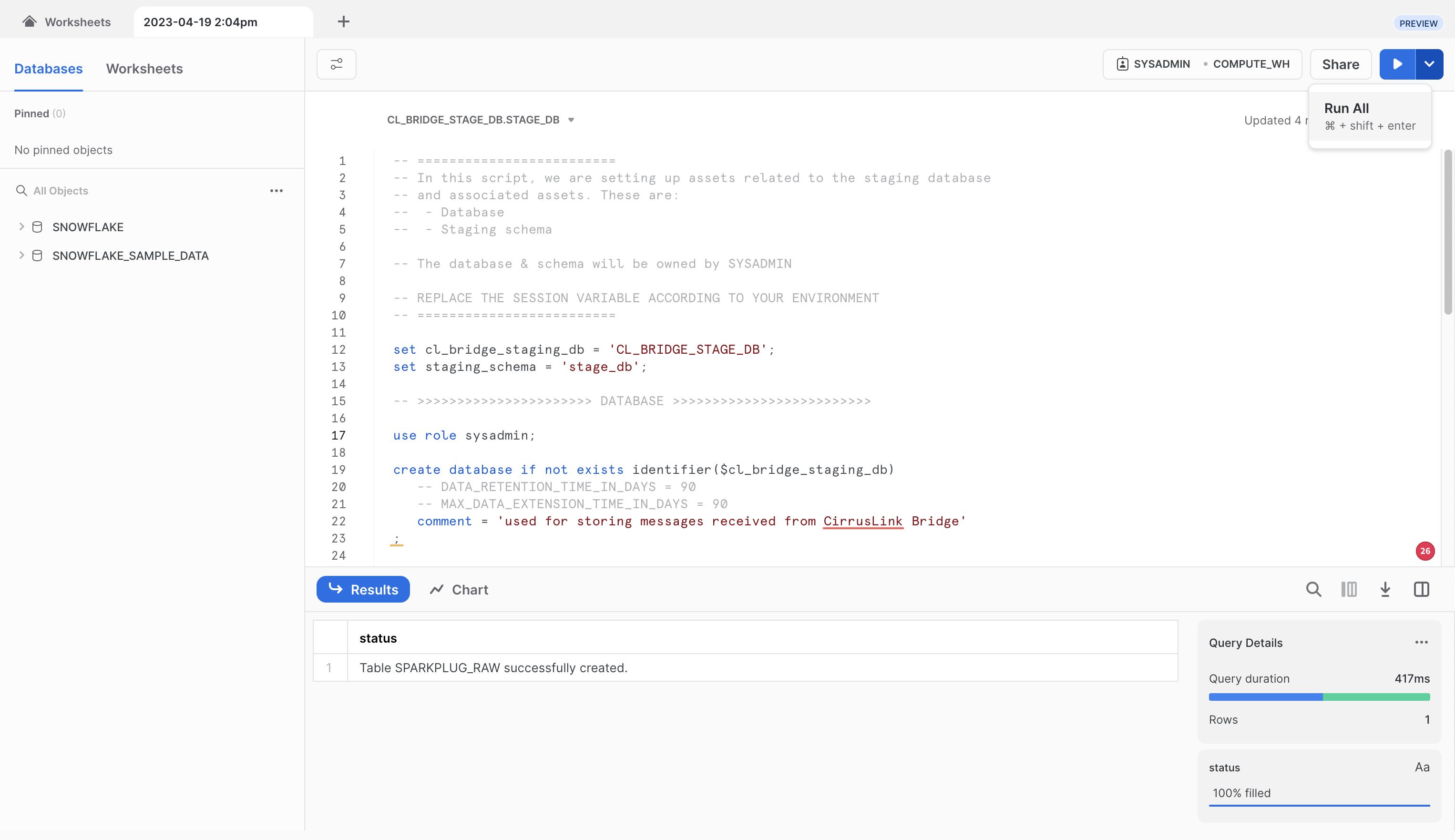 Image Added
Now, repeat the process for each of the following scripts in the Snowflake Setup Scripts in order. Each time, fully replace the contents of the SQL script with the new script and click the 'Run All' button after pasting each script. Make sure no errors are displayed in the Results window after running each script.
SQL Script 02 Expected Result: Stream NBIRTH_STREAM successfully created.
SQL Script 03 Expected Result: Function GENERATE_DEVICE_ASOF_VIEW_DDL successfully created.
SQL Script 04 Expected Result: Function CREATE_EDGE_NODE_SCHEMA successfully created.
SQL Script 05 Expected Result: Function CREATE_ALL_EDGE_NODE_SCHEMAS successfully created.
SQL Script 06 Expected Result: Statement executed successfully.
SQL Script 07 Expected Result: Statement executed successfully.
SQL Script 08 Expected Result: Statement executed successfully.
After all of the scripts have successfully executed, create a new user in Snowflake. This user will be used by IoT Bridge for Snowflake to push data into Snowflake. In the Snowflake Web UI, go to Admin → Users & Roles and then click '+ User' in the upper right hand corner. Give it a username of your choice and a secure password as shown below. For this example we're calling the user IBSNOW_INGEST so we know this user is for ingest purposes. See below for an example and then click 'Create User'.
| Warning |
|---|
| Force user to change password on first time login must be set to False. |
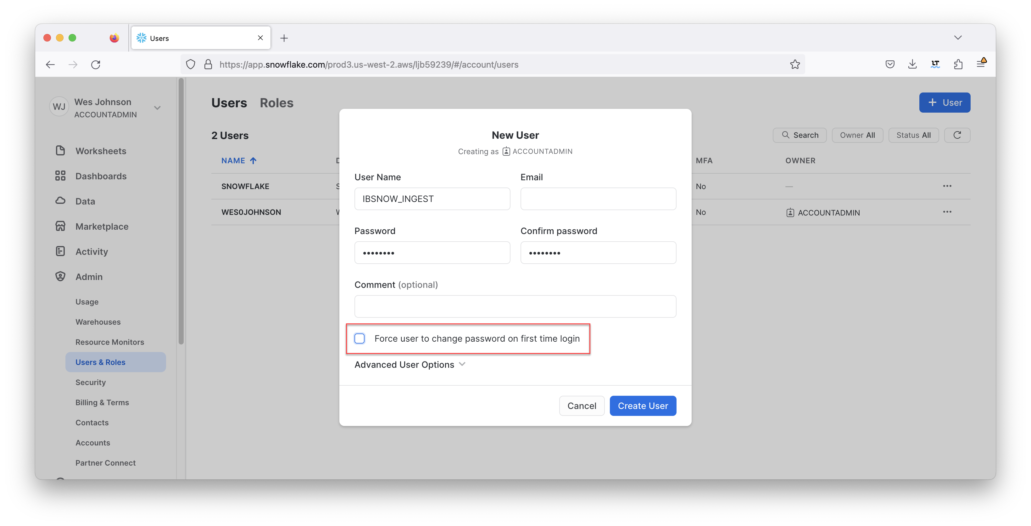 Image Added
In addition, the user must have a specific role to be able to stream data into Snowflake. Click the newly created user to see the following.
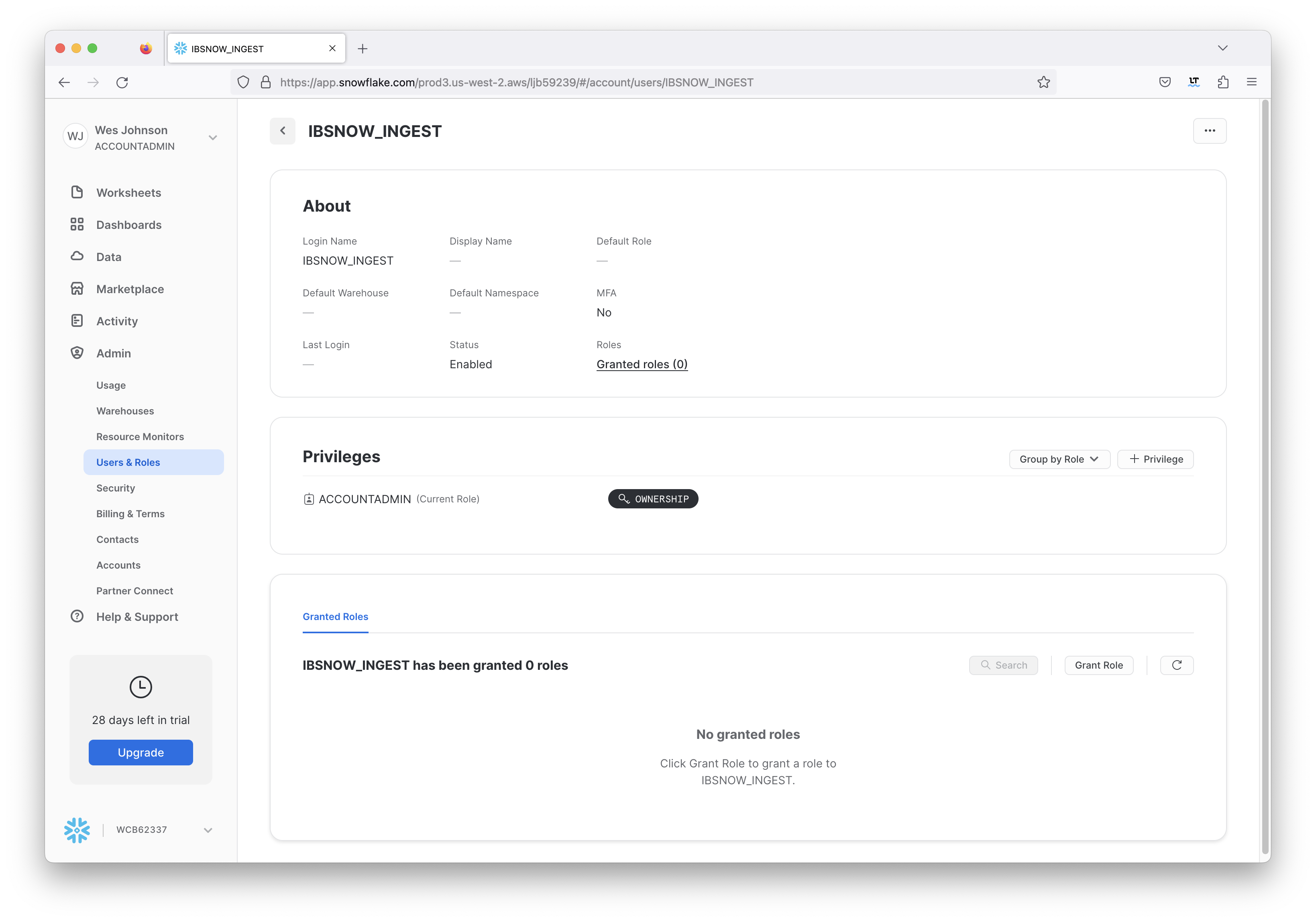 Image Added
In the bottom of the center 'Granted Roles' pane you will see this user has no roles. Click 'Grant Role' to set up a new role. Then, select the 'CL_BRIDGE_PROCESS_RL' role and click 'Grant' as shown below.
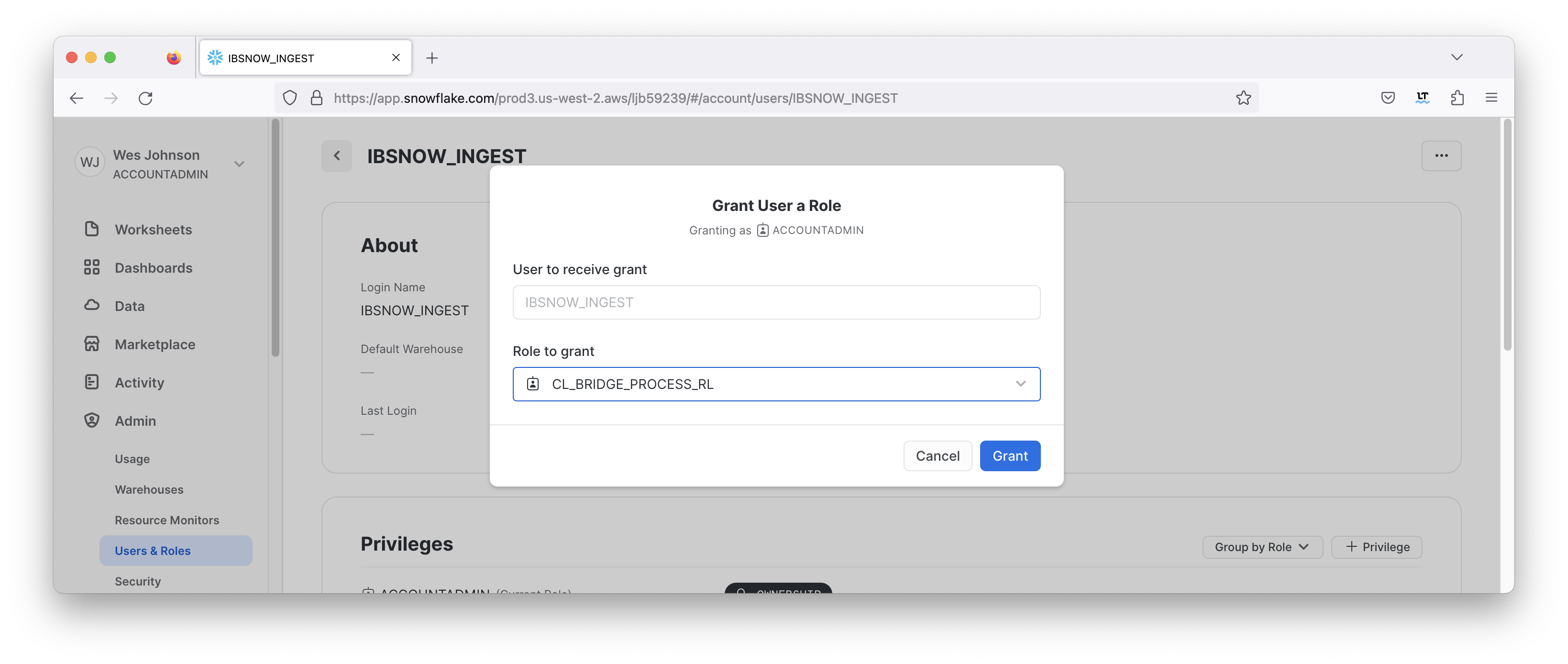 Image Added
After this has been done successfully you will see the role now associated with the new user as shown below.
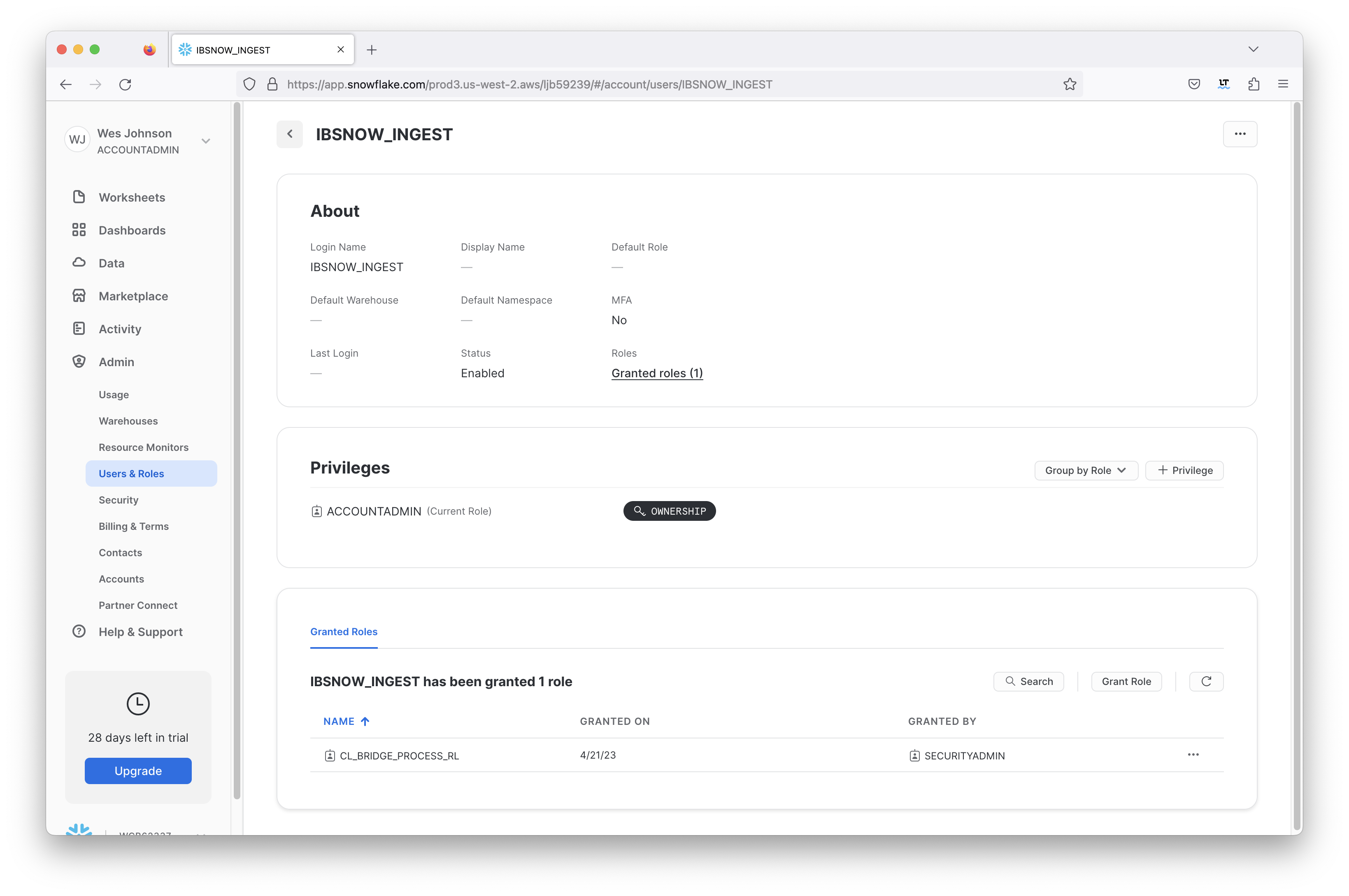 Image Added
Now an unencrypted key pair must be generated and uploaded to Snowflake. This will be used for authentication by the IoT Bridge for Snowflake application to push data to Snowflake via the Snowflake Streaming API.
Attach the generated unencrypted public key to the IBSNOW_INGEST user that we just created for Snowflake ingest purposes.
| Tip |
|---|
See this document for details on how to generate this unencrypted key and assign this to a user in your snowflake account: https://docs.snowflake.com/en/user-guide/key-pair-auth. Note: The step "Configuring the Snowflake Client to User Key Pair Authentication" in the linked tutorial can be skipped. | Warning |
|---|
| The generated key MUST NOT be encrypted |
|
IoT Bridge Setup
First you will need access to the Snowflake IoT Bridge EC2 instance via SSH. See this document for information on how to do this.
Configuring the Snowflake properties
Now, modify the file /opt/ibsnow/conf/ibsnow.properties file. Set the following:
- mqtt_server_url
- mqtt_server_name
- Give it a meaningful name if desired
- mqtt_username
- The username for the MQTT connection if required
- If using Chariot MQTT Server, the default username is 'admin'
- mqtt_password
- The password for the MQTT connection if required
- If using Chariot MQTT Server, the default password is 'changeme'
- primary_host_id
- Set it to a text string such as 'IamHost'
- snowflake_streaming_client_name
- Some text string such as 'MY_CLIENT'
- snowflake_streaming_table_name
- This is the staged_sparkplug_raw_table created by the Snowflake setup in SQL Script 02
- If the default Snowflake setup scripts were used, this is 'SPARKPLUG_RAW'
- snowflake_notify_db_name
- snowflake_notify_schema_name
- snowflake_notify_warehouse_name
- This is the cl_bridge_ingest_wh created by the Snowflake setup in SQL Script 07
- If the default Snowflake setup scripts were used, this is 'cl_bridge_ingest_wh'
When complete, it should look similar to what is shown below.
| Note |
|---|
If you are using self-signed certificates rather than a real signed certificate, you will need to copy the CA certificate chain file uploaded to your MQTT Server to the bridge instance and set - mqtt_ca_cert_chain_path.1
- This is the filepath to the TLS Certificate Authority certificate chain
|
| Excerpt Include |
|---|
| IBSNOW: Snowflake IoT Bridge properties configuration |
|---|
| IBSNOW: Snowflake IoT Bridge properties configuration |
|---|
| nopanel | true |
|---|
|
Configuring the Snowflake streaming profile
Now modify the file /opt/ibsnow/conf/snowflake_streaming_profile.json as described in Setting snowflake_streaming_profile configuration
When complete, it should look similar to what is shown below.
| Excerpt Include |
|---|
| IBSNOW: Setting snowflake_streaming_profile configuration |
|---|
| IBSNOW: Setting snowflake_streaming_profile configuration |
|---|
| nopanel | true |
|---|
|
Now the service can be restarted to pick up the new configuration. Do so by running the following command.
sudo systemctl restart ibsnow |
At this point, IBSNOW should connect to AWS IoT Core and be ready to receive MQTT Sparkplug messages. Verify by running the following command.
tail -f /opt/ibsnow/log/wrapper.log
|
After doing so, you should see something similar to what is shown below. Note the last line is 'MQTT Client connected to ...'. That denotes we have successfully configured IBSNOW and properly provisioned AWS IoT Core.
| Code Block |
|---|
|
INFO|7263/0||23-06-29 20:19:32|20:19:32.932 [Thread-2] INFO  org.eclipse.tahu.mqtt.TahuClient - IBSNOW-8bc00095-9265-41: Creating the MQTT Client to ssl://54.236.16.39:8883 on thread Thread-2
INFO|7263/0||23-06-29 20:19:33|20:19:33.275 [MQTT Call: IBSNOW-8bc00095-9265-41] INFO  org.eclipse.tahu.mqtt.TahuClient - IBSNOW-8bc00095-9265-41: connect with retry succeeded
INFO|7263/0||23-06-29 20:19:33|20:19:33.280 [MQTT Call: IBSNOW-8bc00095-9265-41] INFO  org.eclipse.tahu.mqtt.TahuClient - IBSNOW-8bc00095-9265-41: Connected to ssl://54.236.16.39:8883
INFO|7263/0||23-06-29 20:19:33|20:19:33.294 [MQTT Call: IBSNOW-8bc00095-9265-41] INFO  o.eclipse.tahu.host.TahuHostCallback - This is a offline STATE message from IamHost - correcting with new online STATE message
FINEST|7263/0||23-06-29 20:19:33|20:19:33.297 [MQTT Call: IBSNOW-8bc00095-9265-41] INFO  o.eclipse.tahu.host.TahuHostCallback - This is a offline STATE message from IamHost - correcting with new online STATE message
FINEST|7263/0||23-06-29 20:19:33|20:19:33.957 [Thread-2] INFO org.eclipse.tahu.mqtt.TahuClient - IBSNOW-8bc00095-9265-41: MQTT Client connected to ssl://54.236.16.39:8883 on thread Thread-2 |
Edge Setup with Ignition and MQTT Transmission
Install Ignition and MQTT Transmission module
At this point IoT Bridge is configured and ready to receive data. To get data flowing into IBSNOW we'll set up Inductive Automation's Ignition platform along with the MQTT Transmission module from Cirrus Link.
Installation of Ignition is very straightforward following the instructions in the Installing and Upgrading Ignition guide.
With Ignition installed, the Cirrus Link MQTT Transmission module must be installed as a plugin to Ignition. Follow the instructions in our Module Installation guide
Import UDTs and tags
Launch the Ignition Designer to connect to your Ignition instance.
Once it is launched, navigate to the 'default' tag provider in the Tag Browser, expand the tag tree to see the automatically created tags as shown below and delete tags Example Tag and MQTT Quickstart.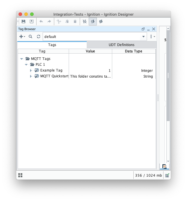 Image Added
from the Designer import these tags IBSNOW_Quickstart_tags.json to MQTT Tags > PLC 1 create a UDT Definition and instance.
You can view the imported UDT Definition and instance in the tag browser:
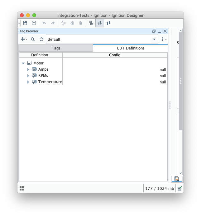 Image Added
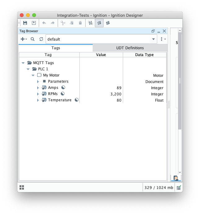 Image Added
At this point, our tags are configured. A UDT definition will map to a model in Snowflake and UDT instances in Ignition will map to Snowflake.
But, before this will happen we need to point MQTT Transmission to the Chariot MQTT Server. To do so, browse back to the Ignition Gateway Web UI and select MQTT Transmission → Settings from the left navigation panel.
Now select the 'Transmitters' tab as shown below.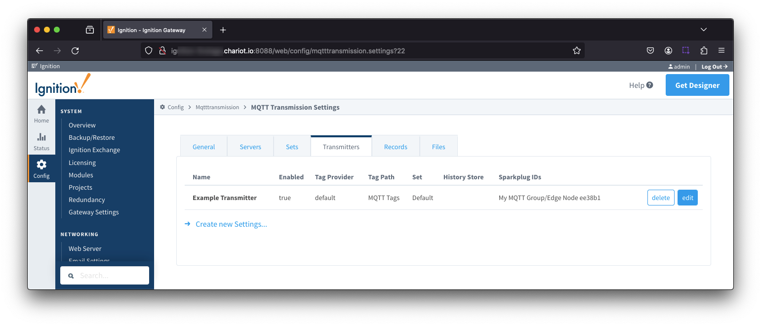 Image Added
Now click the 'edit' button to the right of the 'Example Transmitter'. Scroll down to the 'Convert UDTs' option and uncheck it as shown below. This will also un-grey the 'Publish UDT Definitions' option. Leave it selected as shown below.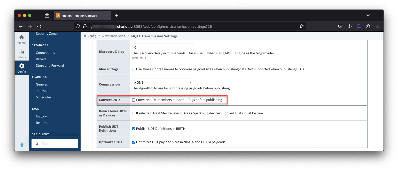 Image Added
Now switch to the 'Servers' and 'Settings' tab. Delete the existing 'Chariot SCADA' pre-seeded MQTT Server Definition. Then create a new one with the following configuration.
- Name
- URL
- Username
- Your username for the Chariot MQTT Server connection
- If using Chariot MQTT Server, the default username is 'admin'
- Password
- Your password for the Chariot MQTT Server connection
- If using Chariot MQTT Server, the default password is 'changeme'
When complete, you should see something similar to the following. However, the 'Connected' state should show '1 of 1' if everything was configured properly.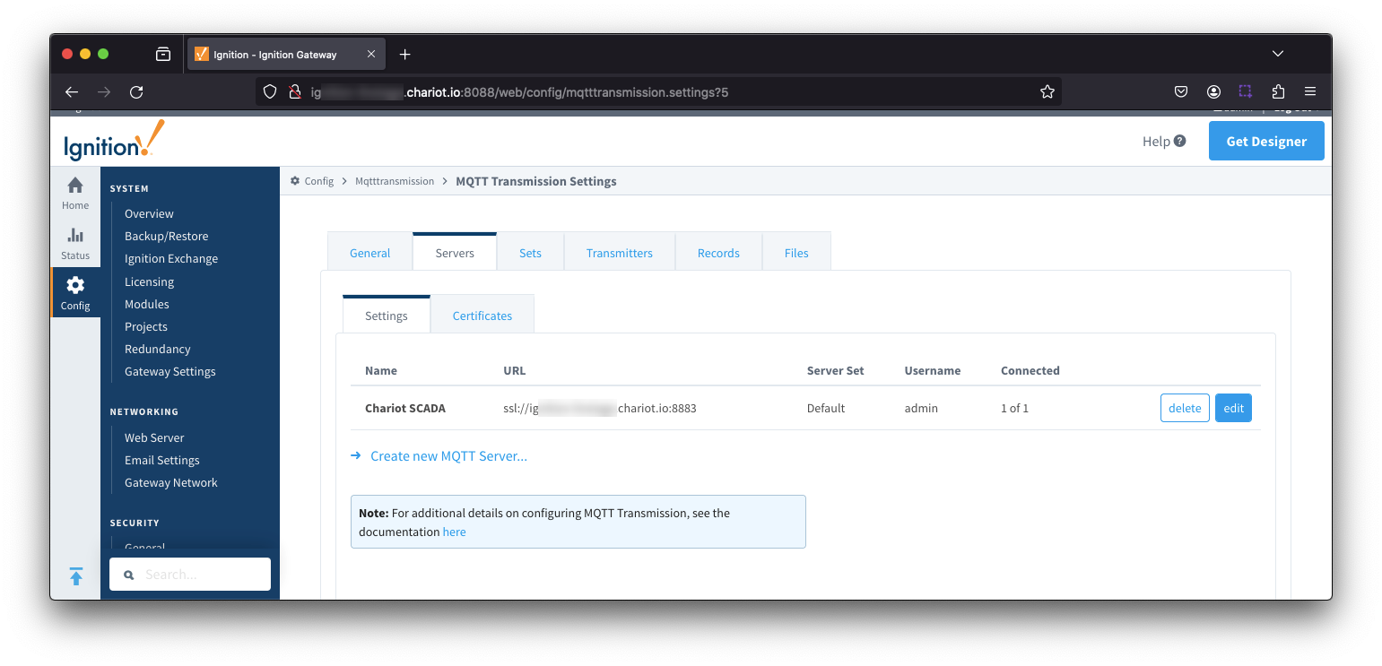 Image Added
At this point, data should be flowing into Snowflake.
By tailing the log in IBSNOW you should see something similar to what is shown below which shows IBSNOW receiving the messages published from Ignition/MQTT Transmission.
When IBSNOW receives the Sparkplug MQTT messages, it creates and updates asset models and assets in Snowflake. The log below is also a useful debugging tool if things don't appear to work as they should.
| Code Block |
|---|
| language | bash |
|---|
| title | Successful Insert |
|---|
|
FINEST|199857/0||23-04-21 15:46:22|15:46:22.951 [TahuHostCallback--3deac7a5] INFO  o.e.tahu.host.TahuPayloadHandler - Handling NBIRTH from My MQTT Group/Edge Node ee38b1
FINEST|199857/0||23-04-21 15:46:22|15:46:22.953 [TahuHostCallback--3deac7a5] INFO  o.e.t.host.manager.SparkplugEdgeNode - Edge Node My MQTT Group/Edge Node ee38b1 set online at Fri Apr 21 15:46:22 UTC 2023
FINEST|199857/0||23-04-21 15:46:23|15:46:23.072 [TahuHostCallback--3deac7a5] INFO  o.e.tahu.host.TahuPayloadHandler - Handling DBIRTH from My MQTT Group/Edge Node ee38b1/PLC 1
FINEST|199857/0||23-04-21 15:46:23|15:46:23.075 [TahuHostCallback--3deac7a5] INFO  o.e.t.host.manager.SparkplugDevice - Device My MQTT Group/Edge Node ee38b1/PLC 1 set online at Fri Apr 21 15:46:22 UTC 2023
FINEST|199857/0||23-04-21 15:46:23|15:46:23.759 [ingest-flush-thread] INFO  n.s.i.s.internal.FlushService - [SF_INGEST] buildAndUpload task added for client=MY_CLIENT, blob=2023/4/21/15/46/rth2hb_eSKU3AAtxudYKnPFztPjrokzP29ZXzv5JFbbj0YUnqUUCC_1049_48_1.bdec, buildUploadWorkers stats=java.util.concurrent.ThreadPoolExecutor@32321763[Running, pool size = 2, active threads = 1, queued tasks = 0, completed tasks = 1]
FINEST|199857/0||23-04-21 15:46:23|15:46:23.774 [ingest-build-upload-thread-1] INFO  n.s.i.i.a.h.io.compress.CodecPool - Got brand-new compressor [.gz]
FINEST|199857/0||23-04-21 15:46:23|15:46:23.822 [ingest-build-upload-thread-1] INFO  n.s.i.streaming.internal.BlobBuilder - [SF_INGEST] Finish building chunk in blob=2023/4/21/15/46/rth2hb_eSKU3AAtxudYKnPFztPjrokzP29ZXzv5JFbbj0YUnqUUCC_1049_48_1.bdec, table=CL_BRIDGE_STAGE_DB.STAGE_DB.SPARKPLUG_RAW, rowCount=2, startOffset=0, uncompressedSize=5888, compressedChunkLength=5872, encryptedCompressedSize=5888, bdecVersion=THREE
FINEST|199857/0||23-04-21 15:46:23|15:46:23.839 [ingest-build-upload-thread-1] INFO  n.s.i.s.internal.FlushService - [SF_INGEST] Start uploading file=2023/4/21/15/46/rth2hb_eSKU3AAtxudYKnPFztPjrokzP29ZXzv5JFbbj0YUnqUUCC_1049_48_1.bdec, size=5888
FINEST|199857/0||23-04-21 15:46:24|15:46:24.132 [ingest-build-upload-thread-1] INFO  n.s.i.s.internal.FlushService - [SF_INGEST] Finish uploading file=2023/4/21/15/46/rth2hb_eSKU3AAtxudYKnPFztPjrokzP29ZXzv5JFbbj0YUnqUUCC_1049_48_1.bdec, size=5888, timeInMillis=292
FINEST|199857/0||23-04-21 15:46:24|15:46:24.148 [ingest-register-thread] INFO  n.s.i.s.internal.RegisterService - [SF_INGEST] Start registering blobs in client=MY_CLIENT, totalBlobListSize=1, currentBlobListSize=1, idx=1
FINEST|199857/0||23-04-21 15:46:24|15:46:24.148 [ingest-register-thread] INFO  n.s.i.s.i.SnowflakeStreamingIngestClientInternal - [SF_INGEST] Register blob request preparing for blob=[2023/4/21/15/46/rth2hb_eSKU3AAtxudYKnPFztPjrokzP29ZXzv5JFbbj0YUnqUUCC_1049_48_1.bdec], client=MY_CLIENT, executionCount=0
FINEST|199857/0||23-04-21 15:46:24|15:46:24.301 [ingest-register-thread] INFO n.s.i.s.i.SnowflakeStreamingIngestClientInternal - [SF_INGEST] Register blob request returned for blob=[2023/4/21/15/46/rth2hb_eSKU3AAtxudYKnPFztPjrokzP29ZXzv5JFbbj0YUnqUUCC_1049_48_1.bdec], client=MY_CLIENT, executionCount=0 |
Data will also be visible in Snowflake at this point. See below for an example. By changing data values in the UDT tags in Ignition DDATA Sparkplug messages will be produced. Every time the Edge Node connects, it will produce NBIRTH and DBIRTH messages. All of these will now appear in Snowflake with their values, timestamps, and qualities
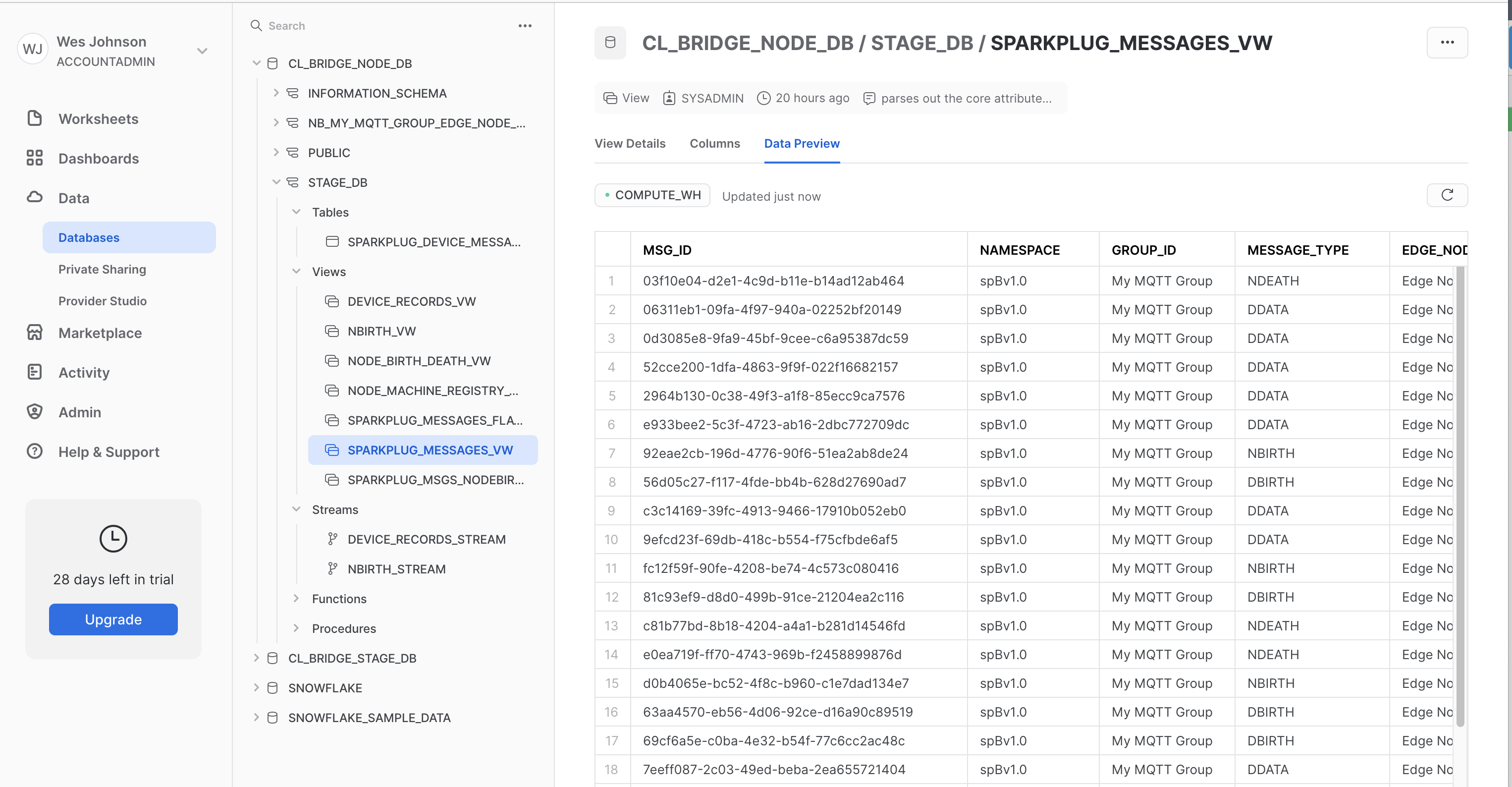 Image Added
Additional Resources
Example JSON document with region and account identifier set in the ARN:
| Code Block |
|---|
{
  "Version": "2012-10-17",
  "Statement": [
    {
      "Effect": "Allow",
      "Action": [
        "iot:Connect",
        "iot:Publish",
        "iot:Subscribe",
        "iot:Receive",
        "iot:RetainPublish"
      ],
      "Resource": "arn:aws:iot:us-west-2:123456789012:*"
    }
  ]
} |
Finally click 'Create' in the lower right. This will show the newly created policy.
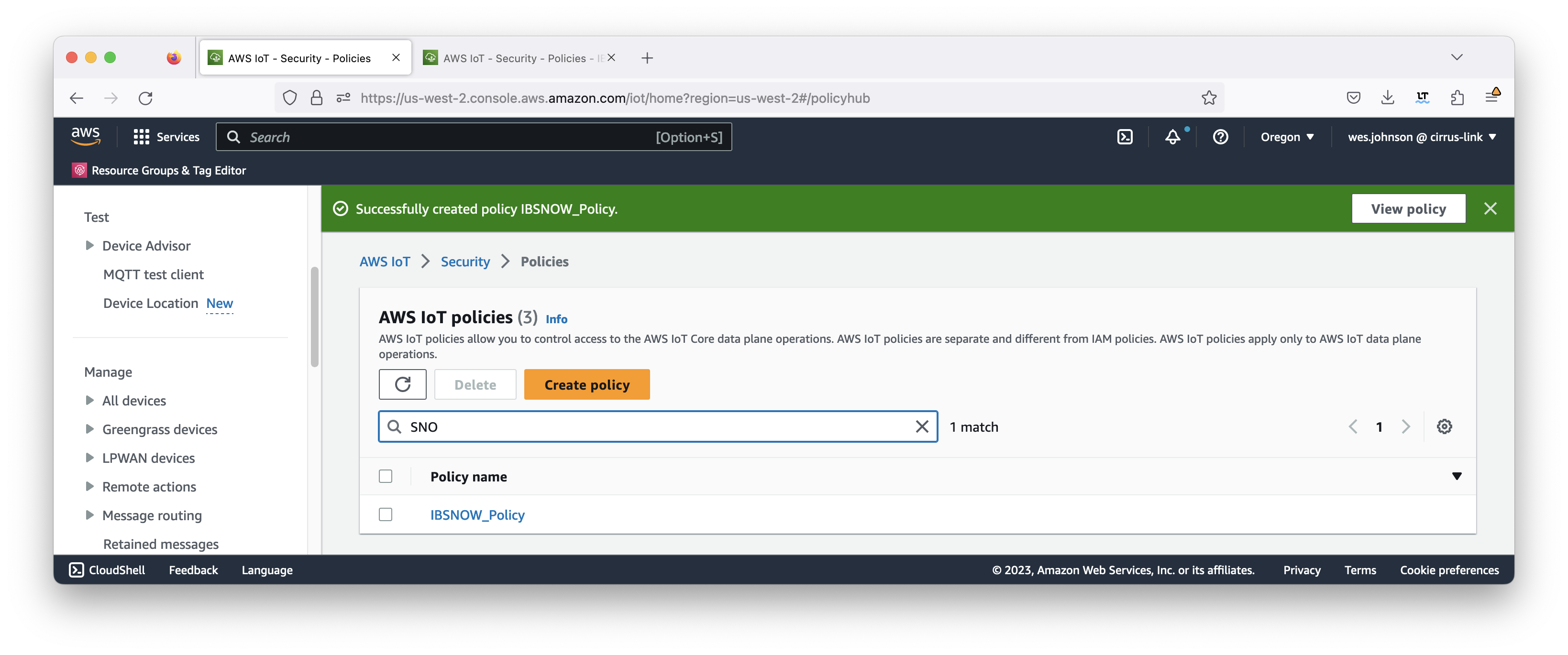 Image Removed
At this point a 'thing' can be created. We'll use the policy a bit later in the procedure. To create the thing, expand 'Manage' on the left navigation panel and click 'All devices → Things' as shown below.
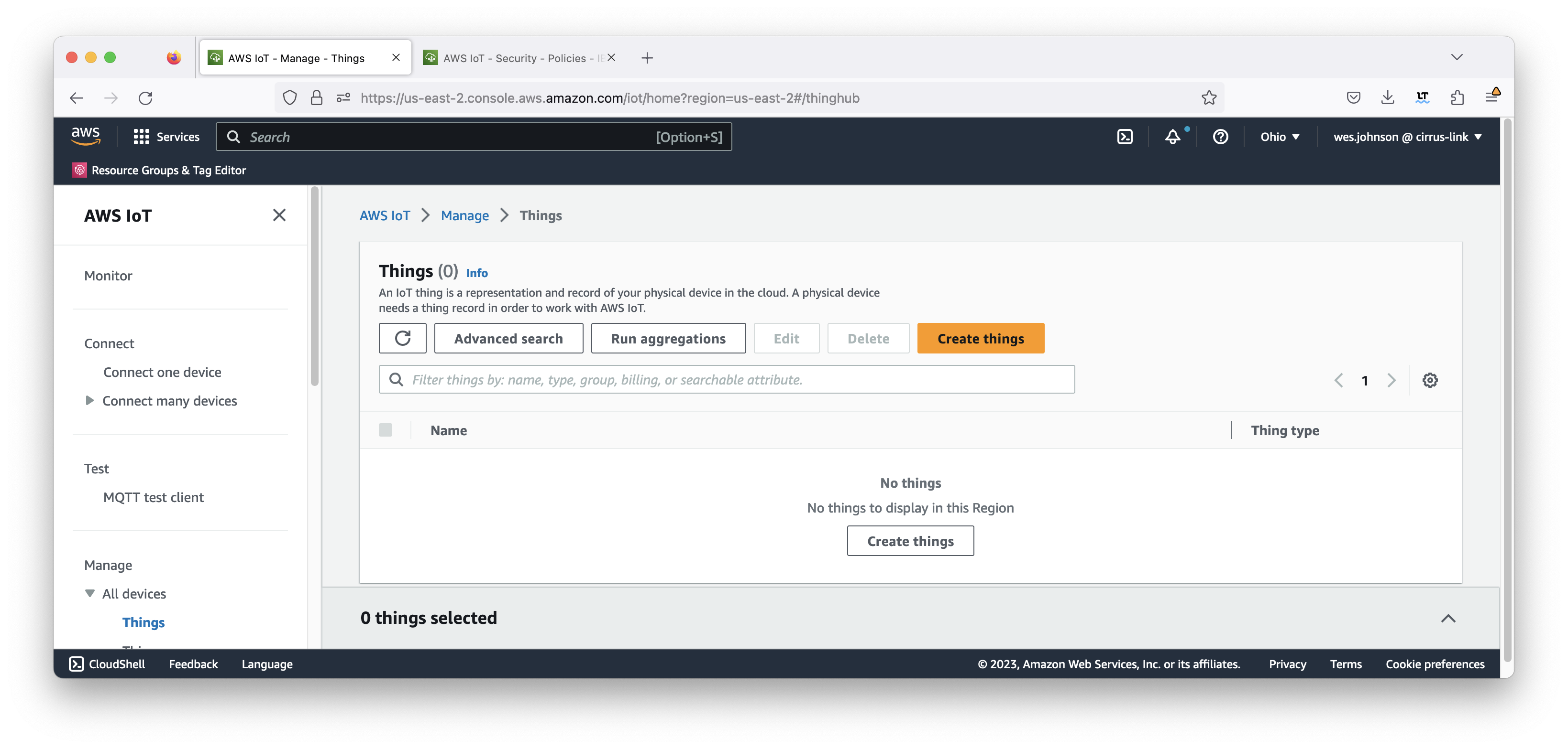 Image Removed
Click 'Create things'. This will bring up the page below.
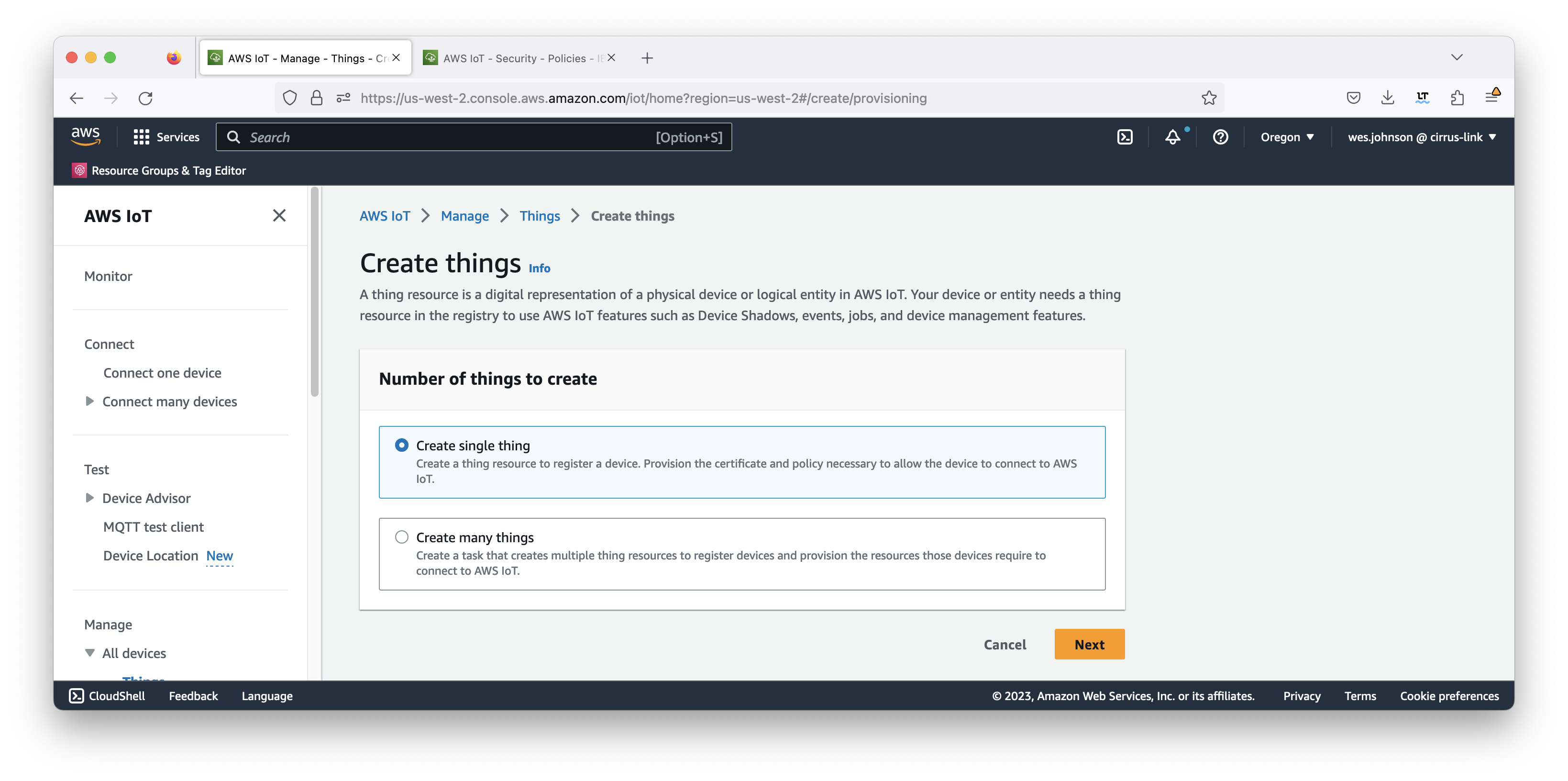 Image Removed
Now click 'Create a single thing'. This will open the following page. Give your thing a name (such as MyEdgeNode) and then click 'Next'.
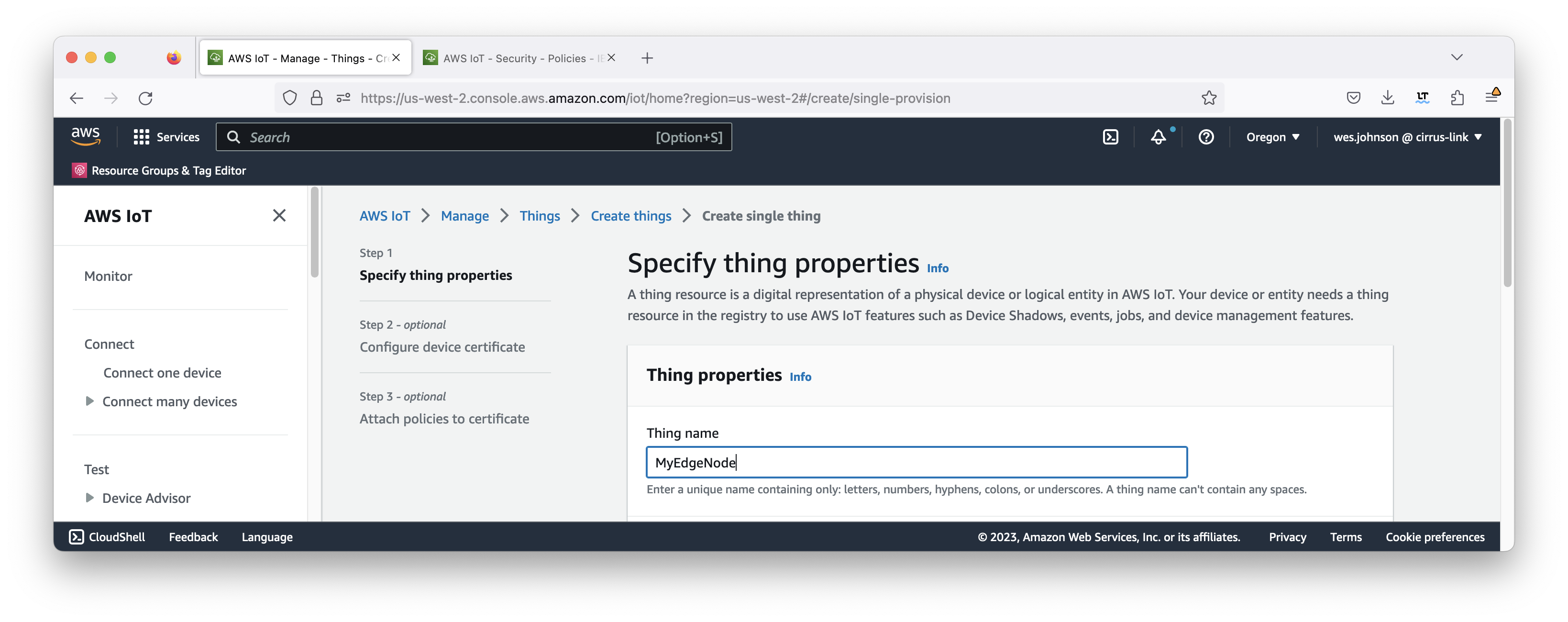 Image Removed
This will bring up the following page. Click the 'Auto-generate a new certificate (recommended)' option shown below.
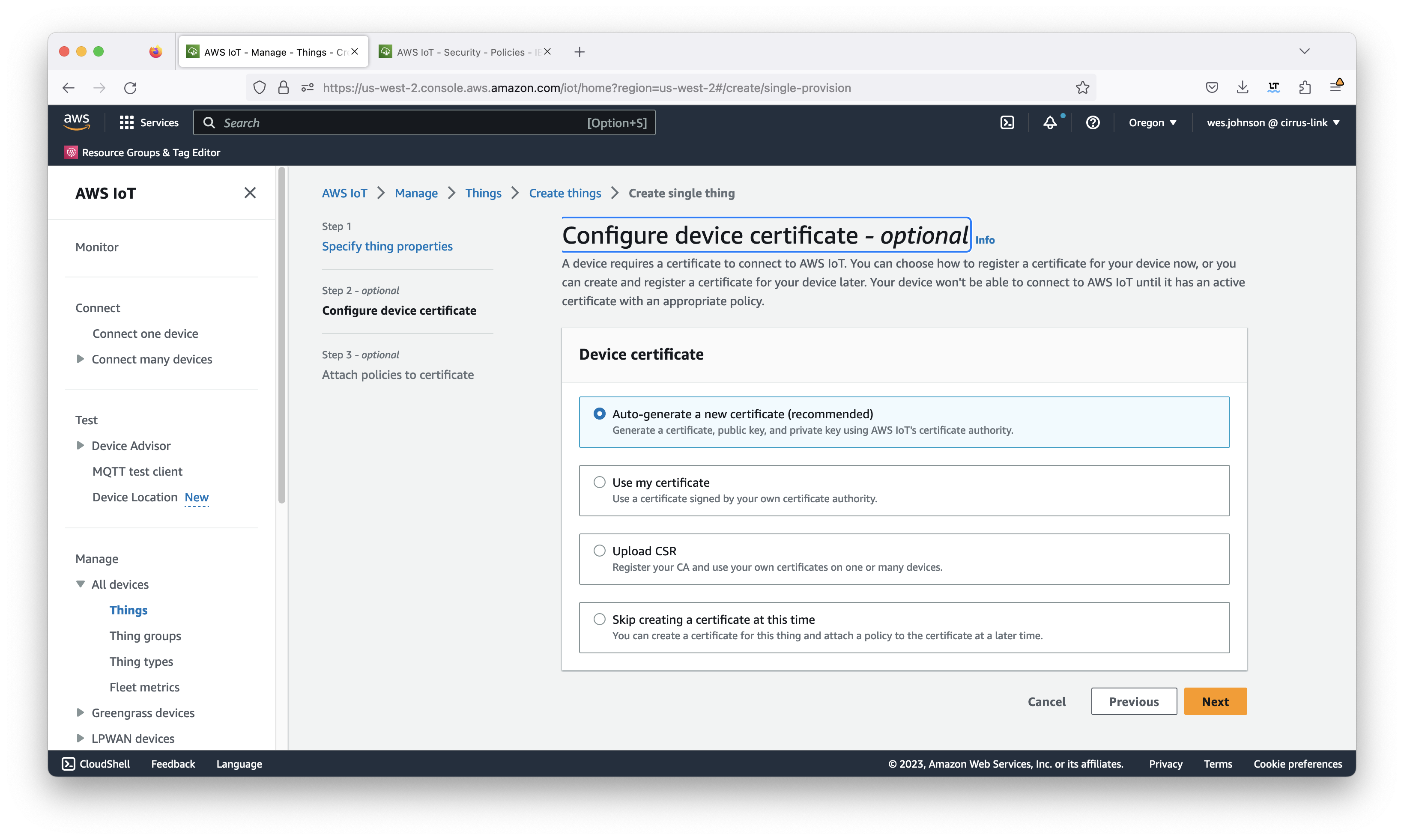 Image Removed
This will bring up the page similar to what is shown below. Select the policy that was created earlier in this tutorial also shown below and click 'Create thing'.
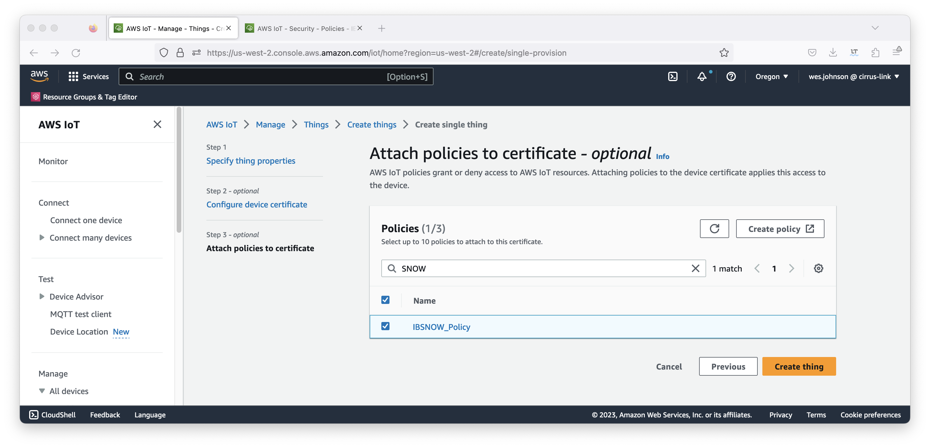 Image Removed
This will show the following download page.
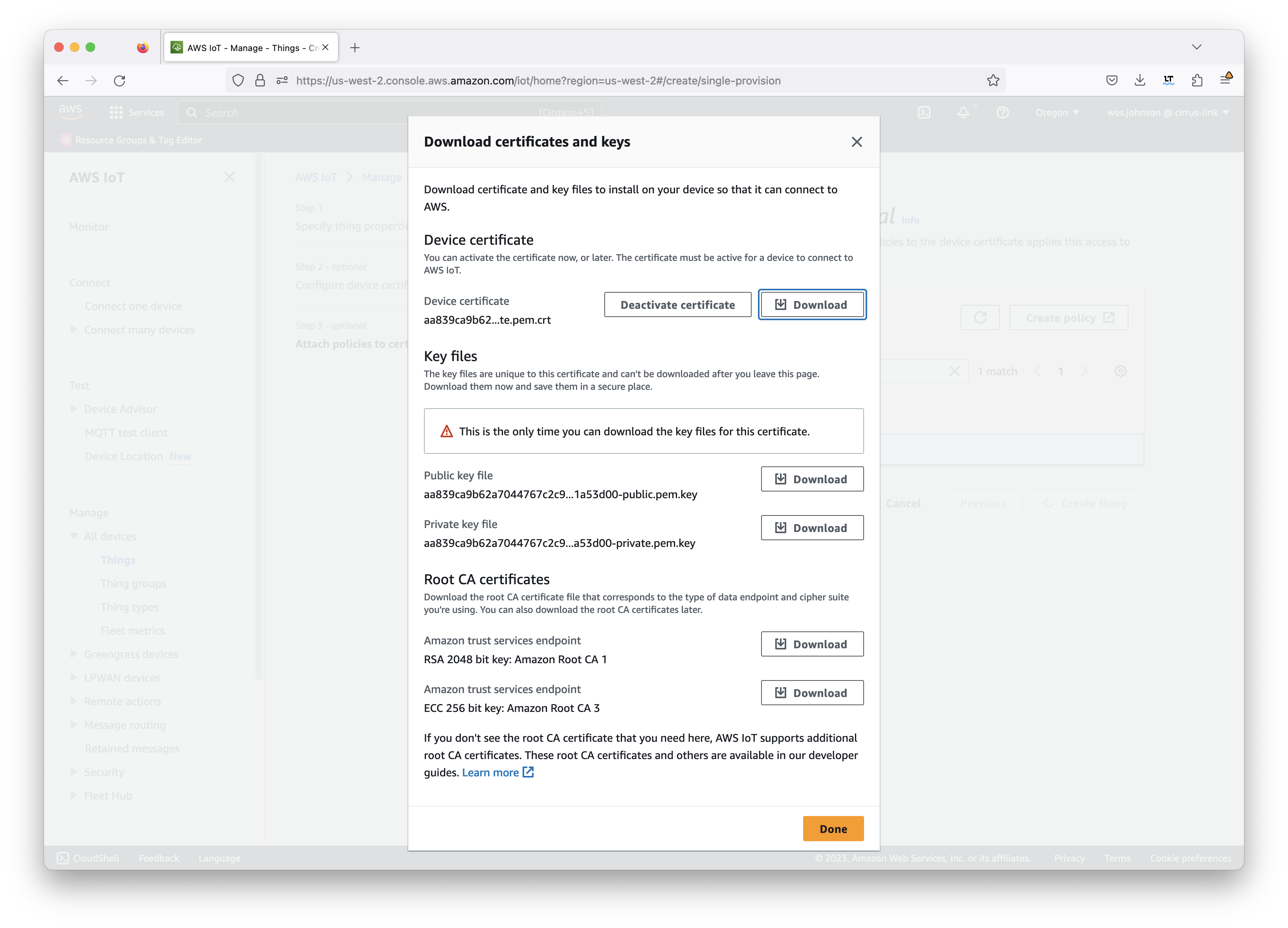 Image Removed
At this point, you must download the following files. Do not proceed until you have downloaded them as you will not get another chance.
- Device certificate
- This file ends in 'certificate.pem.crt'
- Public key file
- This file ends in 'public.pem.key'
- Private key file
- This file ends in 'private.pem.key'
- Root CA certificate
These will all be used in the IBSNOW configuration to connect to AWS IoT later. These files will not be accessible later and must be downloaded now. In addition, there is a link to download the root CA for AWS IoT. Make sure to download this as well. The 'RSA 2048 bit key: Amazon Root CA 1' is the preferred root certificate to download at the time of this writing.
At this point you should have three files where 'UUID' will be some UUID specific to your thing. Do not proceed until you have at least the following three files.
- UUID.certificate.pem.crt
- UUID.private.pem.key
- AmazonRootCA1.pem
Once you have these, click the 'Done' button. This will bring up the following page showing the new thing.
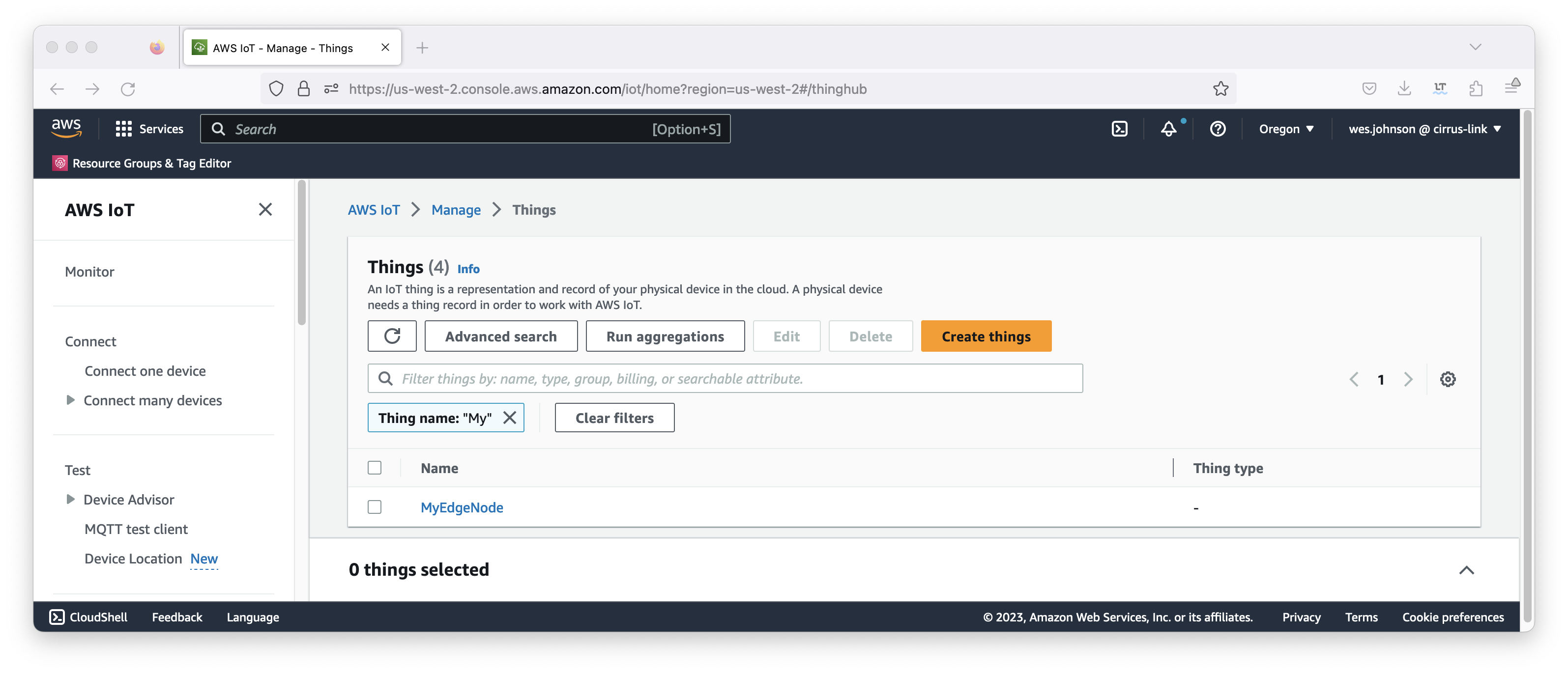 Image Removed
At this point, a thing has been defined with an associated certificate which also has a policy attached to it.
Now we need to get the AWS IoT Core Endpoint. Do so by selecting 'Settings' from the bottom section of the left navigation panel as shown below.
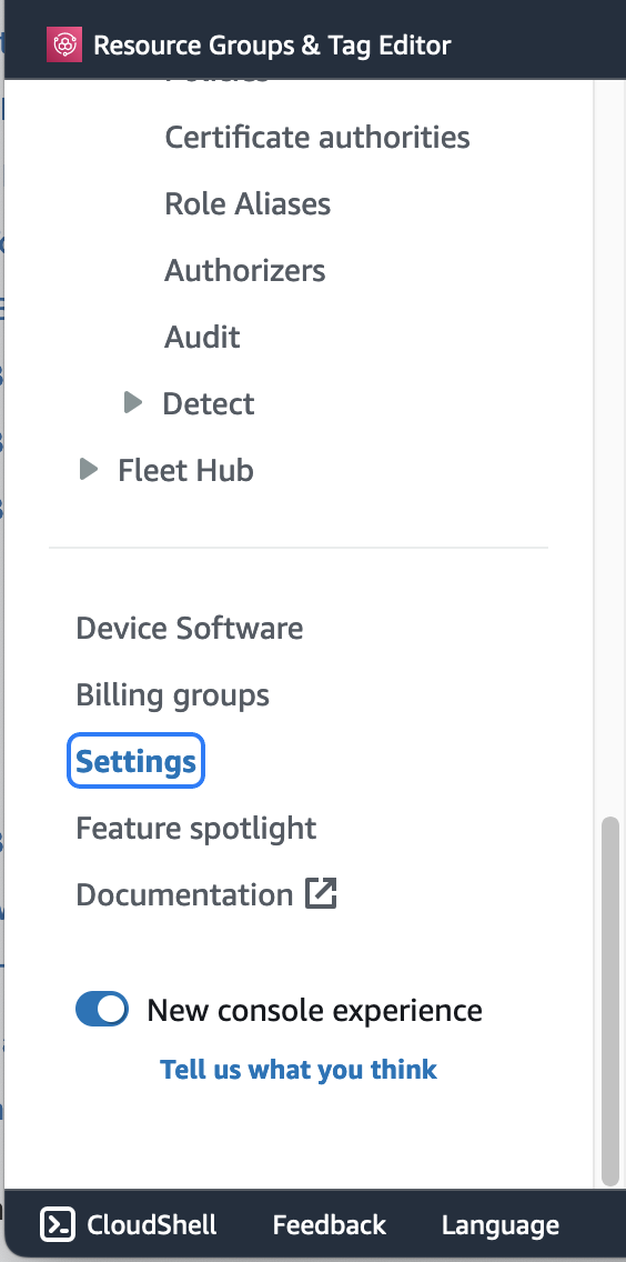 Image Removed
When selected, your AWS IoT Endpoint will be displayed. Note it for future use when configuring IBSNOW.
Snowflake Setup
If you don't have a Snowflake account, open a Web Browser and go to https://www.snowflake.com. Follow the instructions there to start a free trial. After creating an account, log in to Snowflake via the Web Console. You should see something like what is shown below.
Image Removed
Create a new 'SQL Worksheet' by clicking the blue + button in the upper right hand corner of the window as shown below.
Image Removed
Copy and paste the following SQL script into the center pane. Click the 'expand' button on the right to
| Code Block |
|---|
|
-- =========================
-- In this script, we are setting up assets related to the staging database
-- and associated assets. These are:
--  - Database
--  - Staging schema

-- The database & schema will be owned by SYSADMIN

-- REPLACE THE SESSION VARIABLE ACCORDING TO YOUR ENVIRONMENT
-- =========================

set cl_bridge_staging_db = 'CL_BRIDGE_STAGE_DB';
set staging_schema = 'stage_db';

-- >>>>>>>>>>>>>>>>>>>>>> DATABASE >>>>>>>>>>>>>>>>>>>>>>>>>

use role sysadmin;

create database if not exists identifier($cl_bridge_staging_db)
   -- DATA_RETENTION_TIME_IN_DAYS = 90
   -- MAX_DATA_EXTENSION_TIME_IN_DAYS = 90
   comment = 'used for storing messages received from CirrusLink Bridge'
;

-- >>>>>>>>>>>>>>>>>>>>>> STAGING SCHEMA >>>>>>>>>>>>>>>>>>>>>>>>>

use database identifier($cl_bridge_staging_db);

create schema if not exists identifier($staging_schema)
  with managed access
  -- data_retention_time_in_days = 90
  -- max_data_extension_time_in_days = 90
  comment = 'Used for staging data direct from CirrusLink Bridge';

-- >>>>>>>>>>>>>>>>>>>>>> STAGING SCHEMA ASSETS >>>>>>>>>>>>>>>>>>>>>>>>>

use schema identifier($staging_schema);

-- =========================
-- Define tables
-- =========================

create or replace table sparkplug_raw (
    uuid varchar
    ,msg_topic varchar
    ,namespace varchar
    ,group_id varchar
    ,msg_type varchar
    ,edge_node_id varchar
    ,device_id varchar
    ,msg variant
    ,inserted_at number
)
change_tracking = true
cluster by (msg_type ,group_id ,edge_node_id ,device_id)
comment = 'Used for storing json messages from sparkplug bridge/gateway'
; |
After pasting the code into the center pane of the SQL Worksheet, click the drop down arrow next to the blue play button in the upper right corner of the window and click 'Run All' as shown below.
Image Removed
After doing so, you should see a message in the 'Results' pane denoting the SPARKPLUG_RAW table was created successfully as shown below.
Image Removed
Now, repeat the process for each of the following scripts in order. Each time, fully replace the contents of the SQL script with the new script and click the 'Run All' button after pasting each script. Make sure no errors are displayed in the Results window after running each script.
IoT Bridge Setup
With AWS IoT and Snowflake now properly provisioned and IBSNOW installed, IBSNOW must be configured. To configure it, you must be able to access it via SSH. Ensure you can access it via the Access Instructions here. Once you can access it, you must copy the three certificate files you captured when provisioning the AWS IoT Core thing. Again, these files are:
- UUID.certificate.pem.crt
- UUID.private.pem.key
- AmazonRootCA1.pem
On the target EC2 instance, the following directory exists to hold the certificates.
...
/opt/ibsnow/conf/certs
Now copy the three files to the /opt/ibsnow/conf/certs directory. When done, it should look similar to what is shown below.
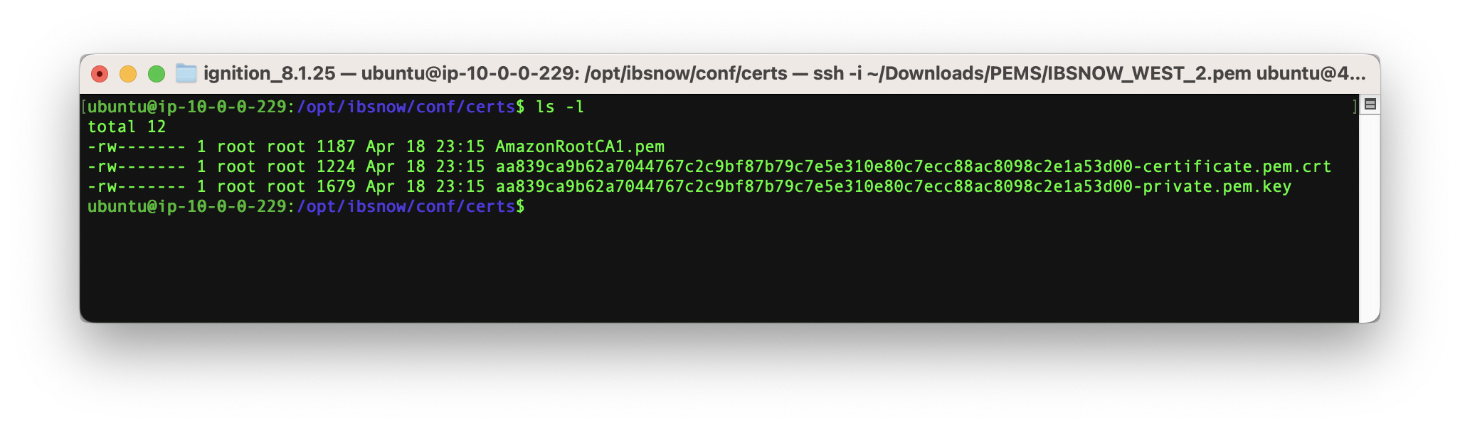 Image Removed
Note the files should be owned by root and not readable by other users. To set the ownership and permissions as shown above, run the following commands.
| Code Block |
|---|
|
sudo chown root:root /opt/ibsnow/conf/certs/*
sudo chmod 600 /opt/ibsnow/conf/certs/* |
Now, modify the file /opt/ibsnow/conf/ibsnow.properties file. Set the following:
- mqtt_server_url
- mqtt_ca_cert_chain_path
- The path to the AWS root CA certificate
- mqtt_client_cert_path
- The path to the AWS thing certificiate
- mqtt_client_private_key_path
- The path to the AWS thing private key
When complete, it should look similar to what is shown below.
<TODO>Add Image</TODO>
Now the service can be restarted to pick up the new configuration. Do so by running the following command.
sudo /etc/init.d/ibsnow restart
|
At this point, IBSNOW should connect to AWS IoT Core and be ready to receive MQTT Sparkplug messages. Verify by running the following command.
...
tail -f /opt/ibsnow/log/wrapper.log
After doing so, you should see something similar to what is shown below. Note the last line is 'MQTT Client connected to ...'. That denotes we have successfully configured IBSNOW and properly provisioned AWS IoT Core.
<TODO>Add Image</TODO>
...
At this point IoT Bridge is configured and ready to receive data. To get data flowing into IBSNOW we'll set up Inductive Automation's Ignition platform along with the MQTT Transmission module from Cirrus Link. Begin by downloading Ignition here.
https://inductiveautomation.com/downloads
Installation of Ignition is very straightforward and fast. There is a guide to do so here.
https://docs.inductiveautomation.com/display/DOC80/Installing+and+Upgrading+Ignition
With Ignition installed, MQTT Transmission must be installed as well as a plugin to Ignition. Get MQTT Transmission for your version of Ignition here.
https://inductiveautomation.com/downloads/third-party-modules
Now use the procedure below to install the MQTT Transmission module.
https://docs.inductiveautomation.com/display/DOC80/Installing+or+Upgrading+a+Module
With Ignition and MQTT Transmission installed, we can configure the MQTT Transmission module to connect to AWS IoT Core using the same certificates that we provisioned earlier. Begin by clicking 'Get Desginer' in the upper right hand corner of the Ignition Gateway Web UI as shown below.
<TODO>Add Image</TODO>
Now launch the Ignition Designer using the Designer Launcher as shown below.
<TODO>Add Image</TODO>
Once it is launched, you should see something similar to what is shown below. Note the Tag Browser has been expanded and the automatically created example tags have been highlighted.
<TODO>Add Image</TODO>
Begin by deleting these two tags (Example Tag and MQTT Quickstart). Then click the 'UDT Definitions' tab as shown below. We will use this view to create a very simple UDT definition.
<TODO>Add Image</TODO>
Now, click the '+' icon in the upper left corner of the tag browser as shown below and select 'New Data Type'
<TODO>Add Image</TODO>
This will open the following dialog box.
<TODO>Add Image</TODO>
Change the name of the tag to Motor as shown below. Also, note the highlighted 'new member tag' icon in the middle of the dialog. We'll use this to create some member tags.
<TODO>Add Image</TODO>
Now use the 'new member tag' button to create a new 'memory tag' as shown below.
<TODO>Add Image</TODO>
Then, set the following parameters for the new memory tag.
- Name
- Date Type
- Engineering Units
<TODO>Add Image</TODO>
Now create two additional member tags with the following configuration.
- Amps
- Memory tag
- Data Type = Integer
- RPMs
- Memory tag
- Data Type = Integer
When complete, the UDT definition should look as follows.
<TODO>Add Image</TODO>
Now switch back to the 'Tags' tab of the Tag Browser. Right click on the 'PLC 1' folder and select 'New Tag → Data Type Instance → Motor' as shown below.
<TODO>Add Image</TODO>
Now set the name to 'My Motor' as shown below and click OK.
<TODO>Add Image</TODO>
Now, set some values under the instance as shown below.
<TODO>Add Image</TODO>
At this point, our tags are configured. A UDT definition will map to a model in Snowflake and UDT instances in Ignition will map to Snowflake. But, before this will happen we need to point MQTT Transmission to AWS IoT Core. To do so, browse back to the Ignition Gateway Web UI and select MQTT Transmission → Settings from the left navigation panel as shown below.
<TODO>Add Image</TODO>
Now select the 'Transmitters' tab as shown below.
<TODO>Add Image</TODO>
Now click the 'edit' button to the right of the 'Example Transmitter'. Scroll down to the 'Convert UDTs' option and uncheck it as shown below. This will also un-grey the 'Publish UDT Defintions' option. Leave it selected as shown below.
<TODO>Add Image</TODO>
Then select the 'Servers' tab and 'Certificates' tab as shown below.
<TODO>Add Image</TODO>
Now upload the three certificate files that were acquired during the AWS IoT thing provisioning. Upload all three to the MQTT Transmission configuration. When done, you should see something similar to what is shown below.
<TODO>Add Image</TODO>
Now switch to the 'Servers' and 'Settings' tab. Delete the existing 'Chariot SCADA' pre-seeded MQTT Server Definition. Then create a new one with the following configuration.
- Name
- URL
- CA Certificate File
- The AWS Root CA certificate
- Client Certificate File
- The AWS client certificate for your provisioned 'thing'
- Client Private Key File
- The AWS client private key for your provisioned 'thing'
When complete, you should see something similar to the following. However, the 'Connected' state should show '1 of 1' if everything was configured properly.
<TODO>Add Image</TODO>
At this point, data should be flowing into Snowflake. By tailing the log in IBSNOW you should see something similar to what is shown below. This shows IBSNOW receiving the messages published from Ignition/MQTT Transmission. When IBSNOW receives the Sparkplug MQTT messages, it creates and updates asset models and assets in Snowflake. The log below is also a useful debugging tool if things don't appear to work as they should.
<TODO>Add Image</TODO>
<TODO>SHOW DATA IN SNOWFLAKE</TODO>
Additional Resources