You are viewing an old version of this page. View the current version.

Compare with Current View Page History

« Previous Version 24 Next »

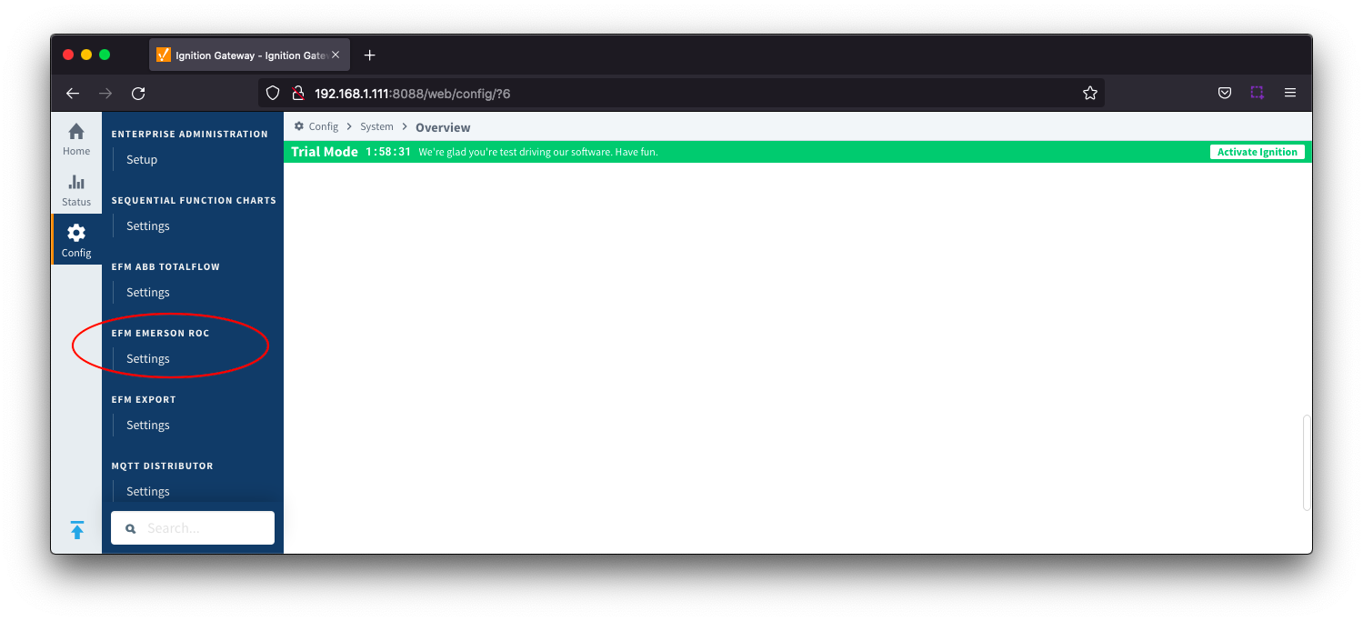
EFM Emerson ROC provides a configuration section to the Ignition Gateway and this can be seen in the left side menu bar of the Ignition Gateway web UI. 

Once configured, a device connection must be created and TLP definitions, templates and poll groups must be created. 

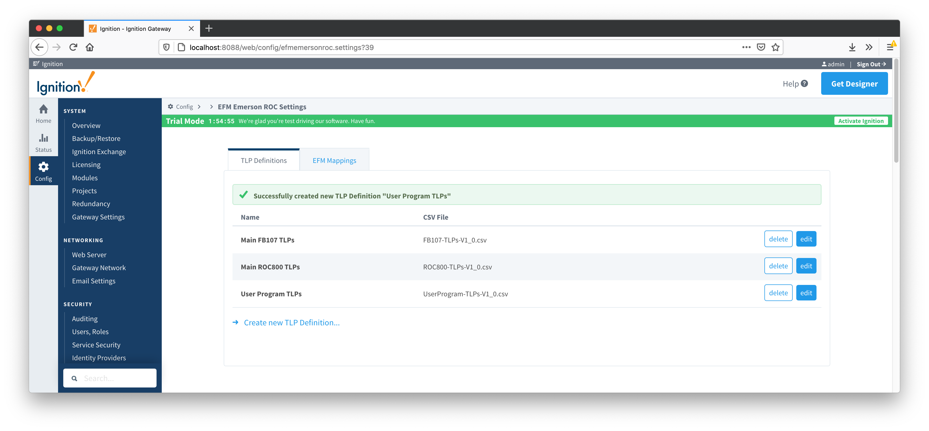
The configuration options for each of the two tabs - TLP Definitions and EFM Mappings are detailed below. 

The Cirrus Link default TLP Definitions and EFM Mapping files can be used as a starting point for configuring the EFM Emerson ROC module.

Download Here

(Note these need to be thoroughly tested and reviewed in your application before they are put into production)

Zip file contents:

  • TLP Definitions
    • FB107-TLPs-V1_0.csv
    • ROC800-TLPs-V1_0.csv
    • UserProgram-TLPs-V1_0.csv
  • EFM Mappings
    • Configuration Mappings
      • FB107-Meter_Configuration_Mapping-V1_0.csv
      • ROC800-Meter_Configuration_Mapping-V1_0.csv
    • Periodic Mappings
      • FB107-Orifice_Turbine_Meter_Periodic_History_Mapping-V1_0.csv
      • ROC800-Orifice_Turbine_Meter_Periodic_History_Mapping-V1_0.csv

TLP Definitions

The first tab contains settings for creating sets of TLP Definitions:

New TLP Definitions can be created by following the 'Create new TLP Definition' link as shown below:
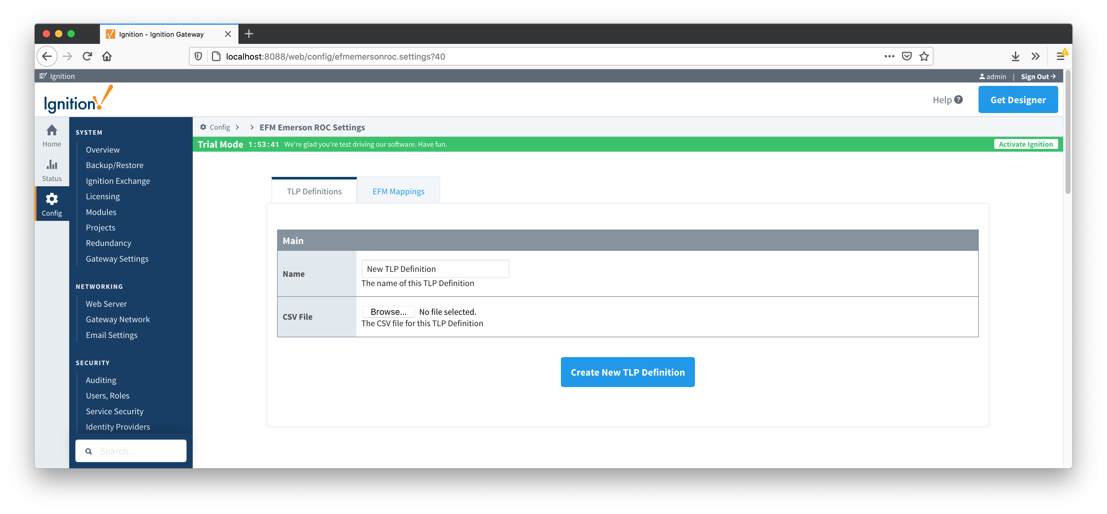
Main Properties

  • Name

    • This is the friendly name of the TLP Definition being created

  • CSV File

    • Click the 'Browse' button to select CSV file for this TLP Definition

EFM Mappings

The EFM Mappings are used for publishing EFM Records representing Events, Alarms, Configuration, and History entries that are polled from a device.

Configuration Mappings

The configuration mapping files are used for building up EFM Configuration Records.  They define which TLPs map to which fields (columns) in an EFM Configuration Record.  Additionally they can provide bit and/or value mappings for the TLP values.  

Review our EFM Emerson ROC Quickstart guide for more details on the content of these configuration mapping files.

The Configuration Mappings tab shows all uploaded Configuration Mapping files.

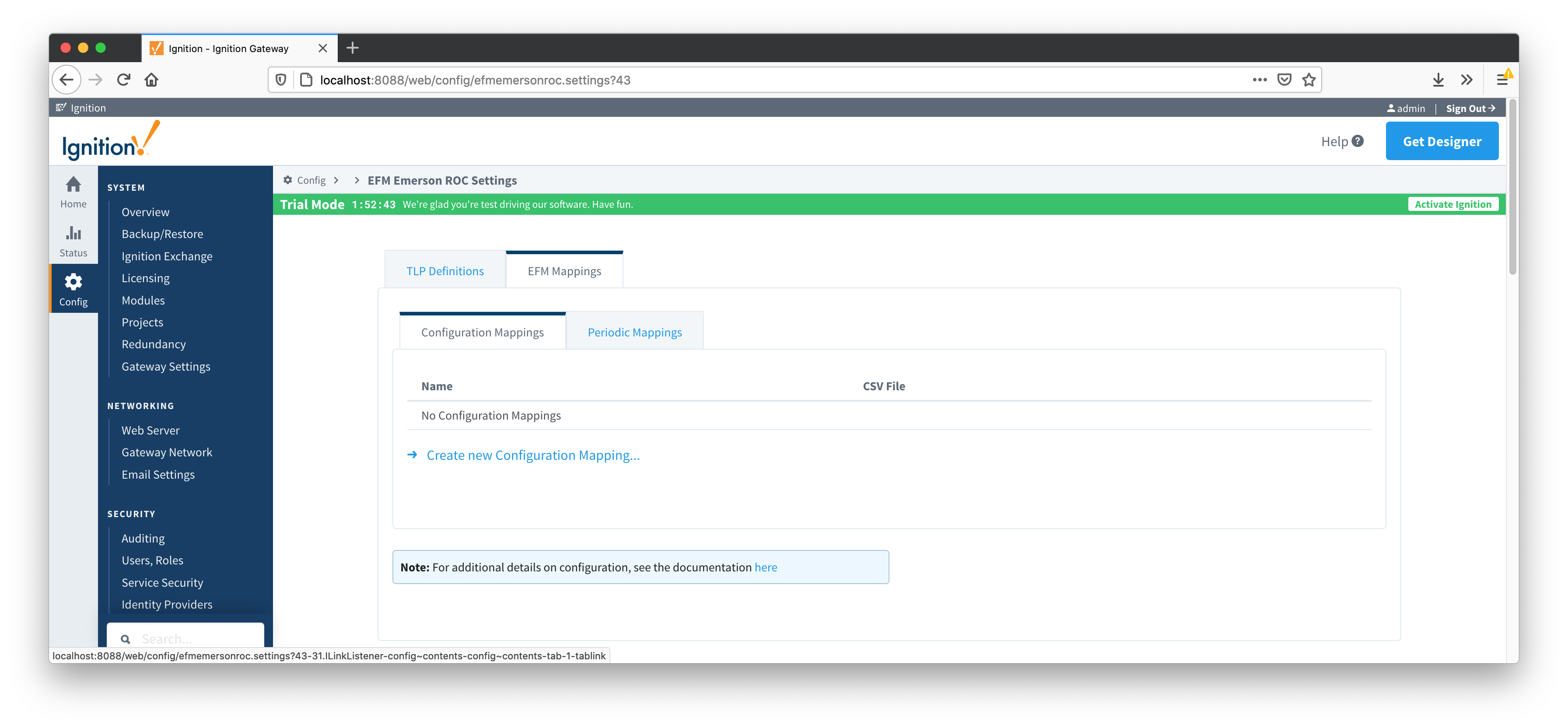
A new Configuration Mapping can be added by clicking on the "Create New Configuration Mapping..." link.
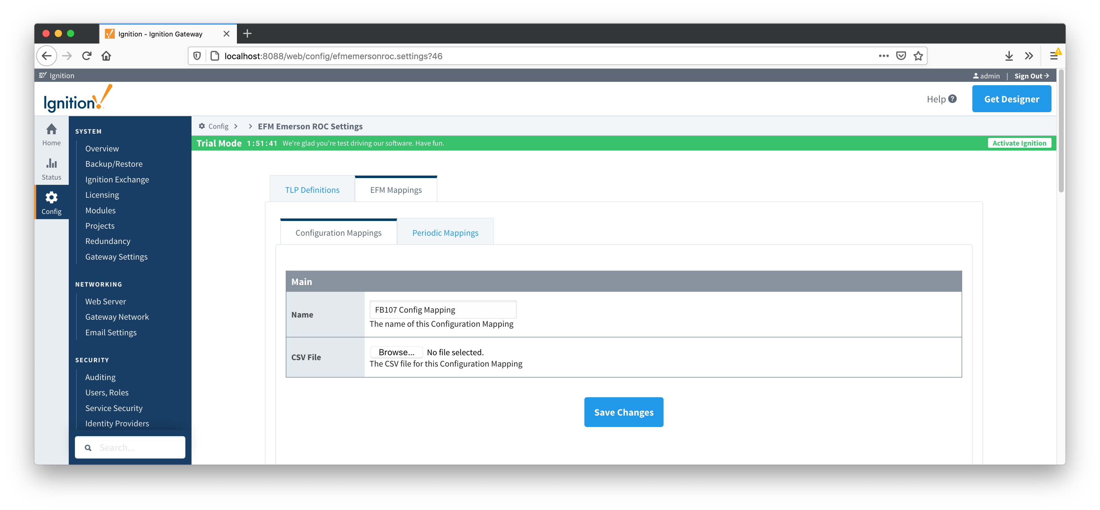
Main Properties

  • Name

    • This is the friendly name of the Configuration Mapping being created

  • CSV File

    • Click the 'Browse' button to select CSV file for this Configuration Mapping

Periodic Mappings

The periodic mapping files are used for building up EFM Periodic History Records.  They define which TLPs map to which fields (columns) in an EFM Periodic History Record, the logical type of the point type table (meter, station, or input), and an archive type of the value.

Review the EFM Emerson ROC Quickstart for more details on the content of these periodic mapping files.

The Periodic Mappings tab shows all uploaded Periodic Mapping files.

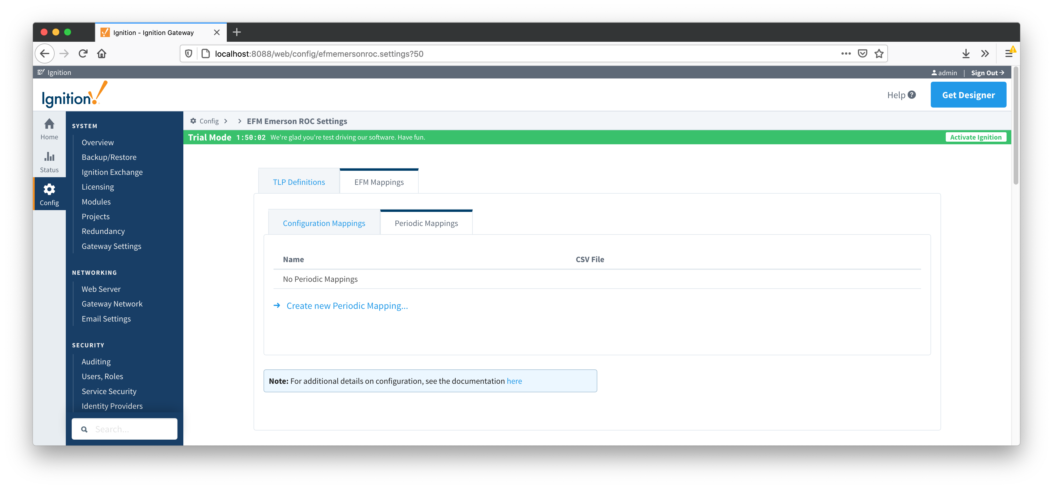
A new Periodic History Mapping can be added by clicking on the "Create New Periodic Mapping..." link.
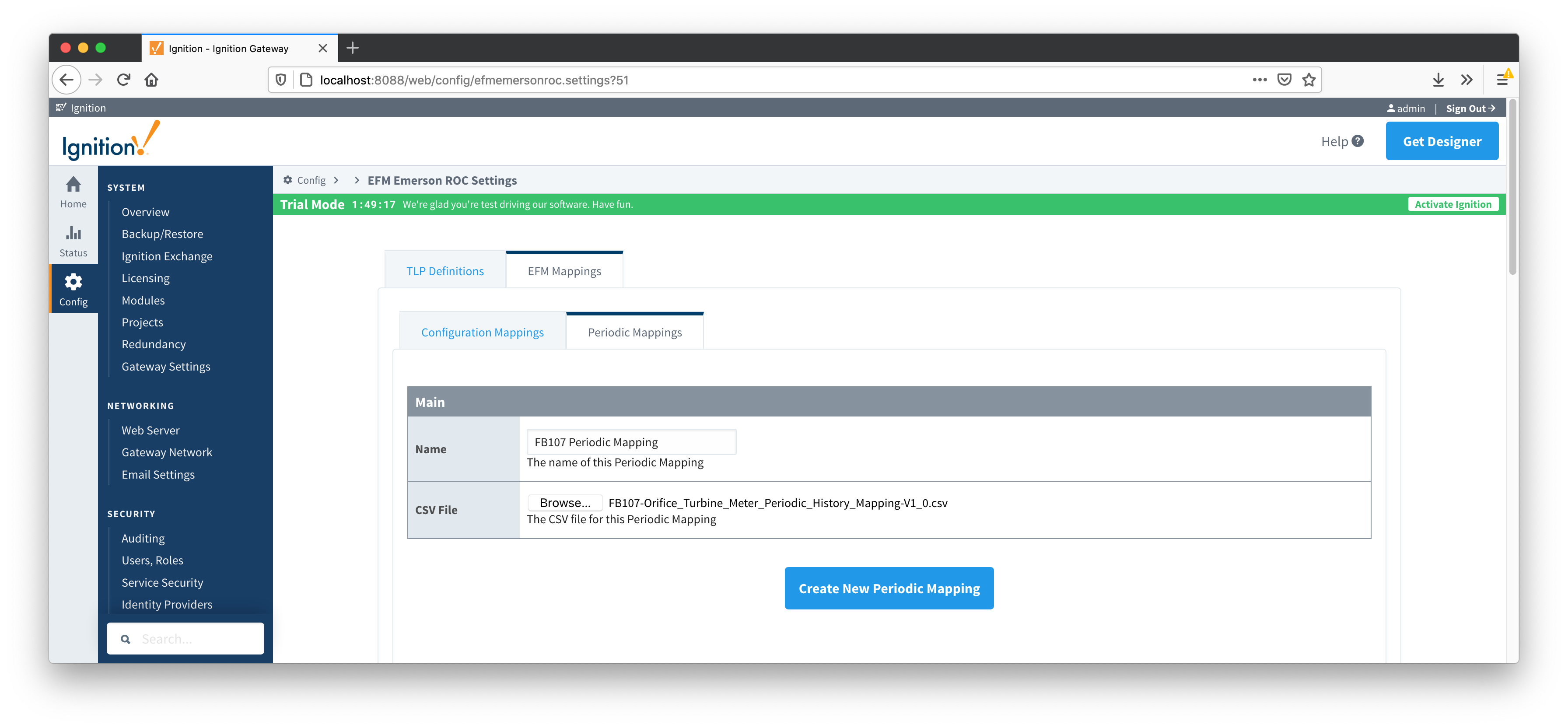
Main Properties

  • Name

    • This is the friendly name of the Periodic Mapping being created

  • CSV File

    • Click the 'Browse' button to select CSV file for this Periodic Mapping

Emerson ROC Device Connection

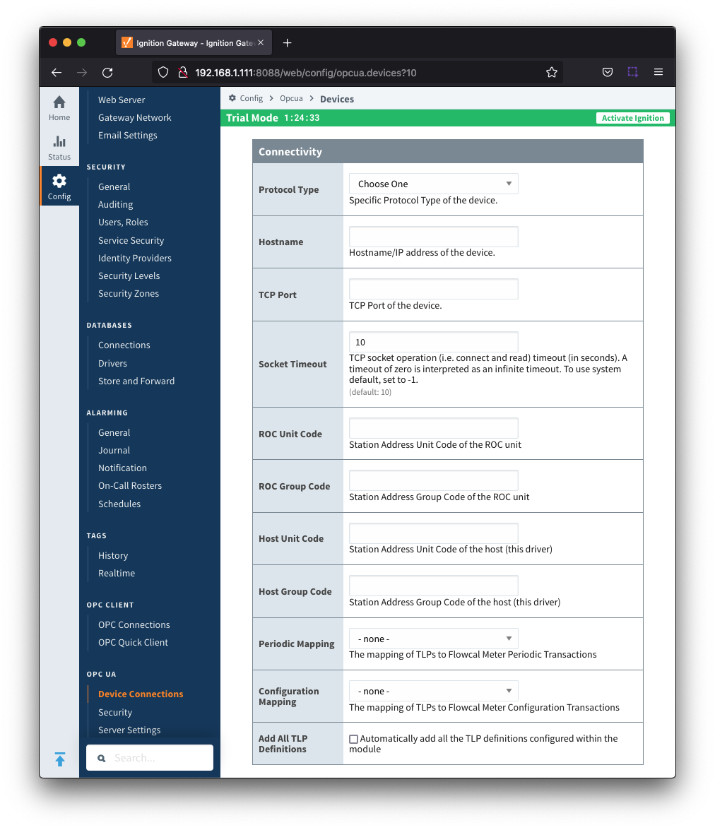
Device connection for Emerson ROC module can be configured via OPC UA configuration.  Begin by selecting OPC UA → Device Connections on the left as shown below:

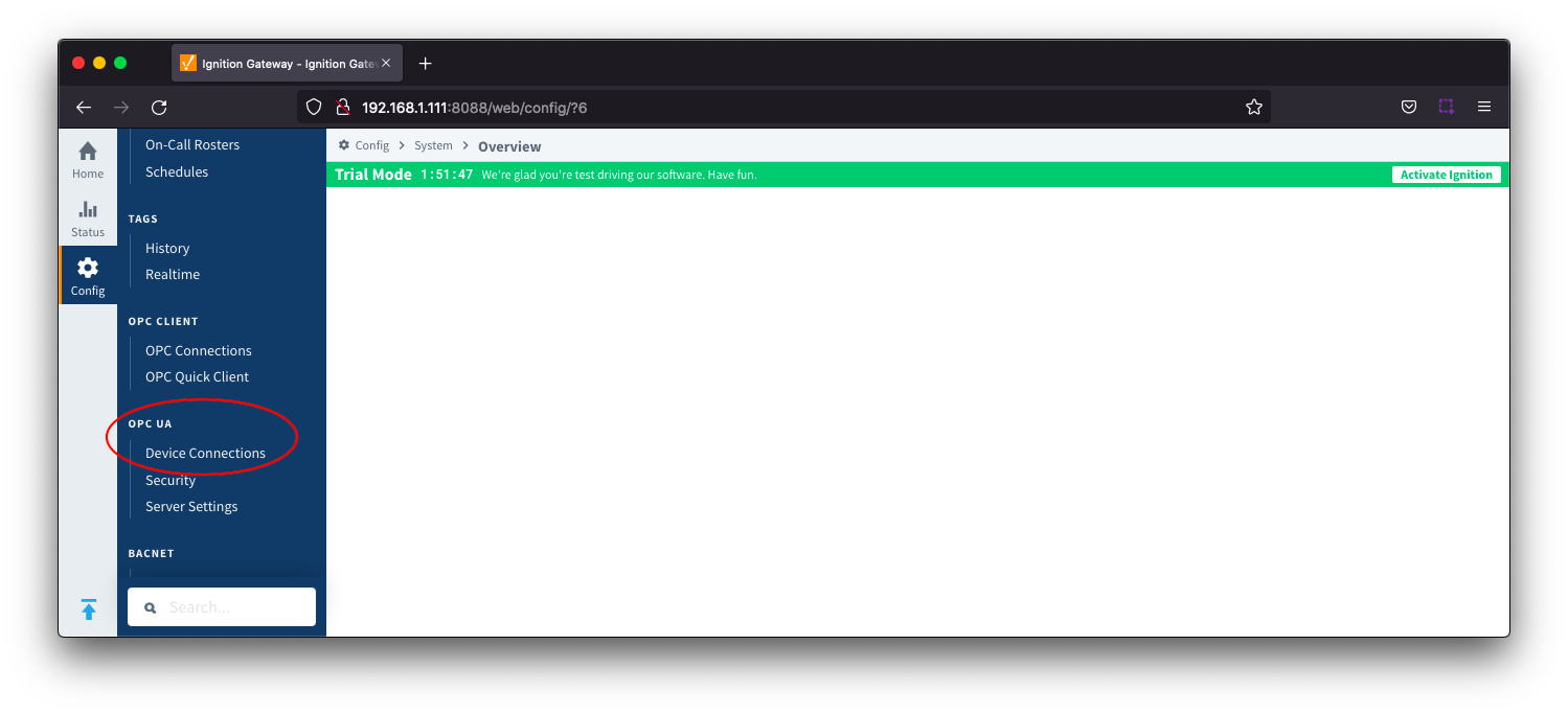
This opens respective configuration page as shown below:

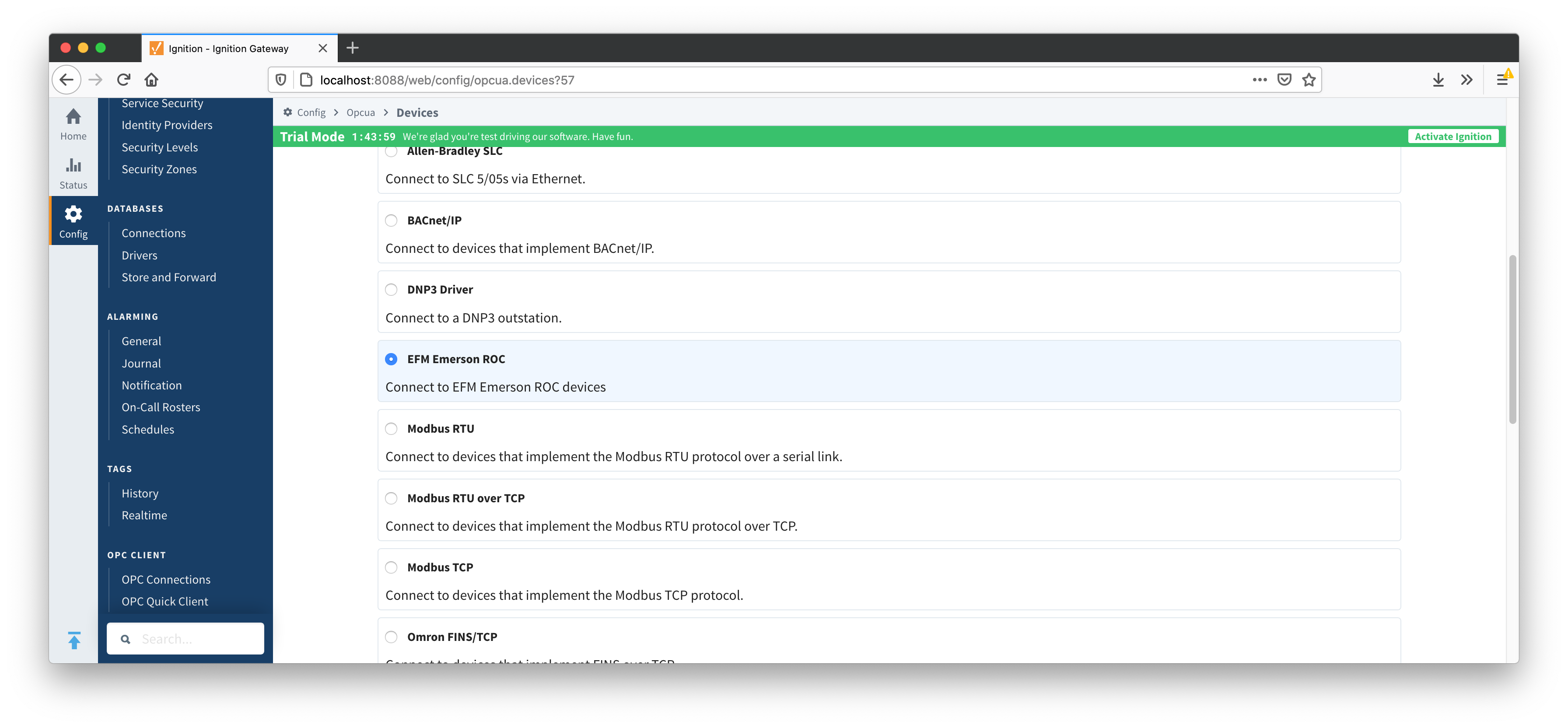
New Emerson ROC device can be created by following the 'Create new Device...' link and choosing 'EFM Emerson ROC' device as shown below:

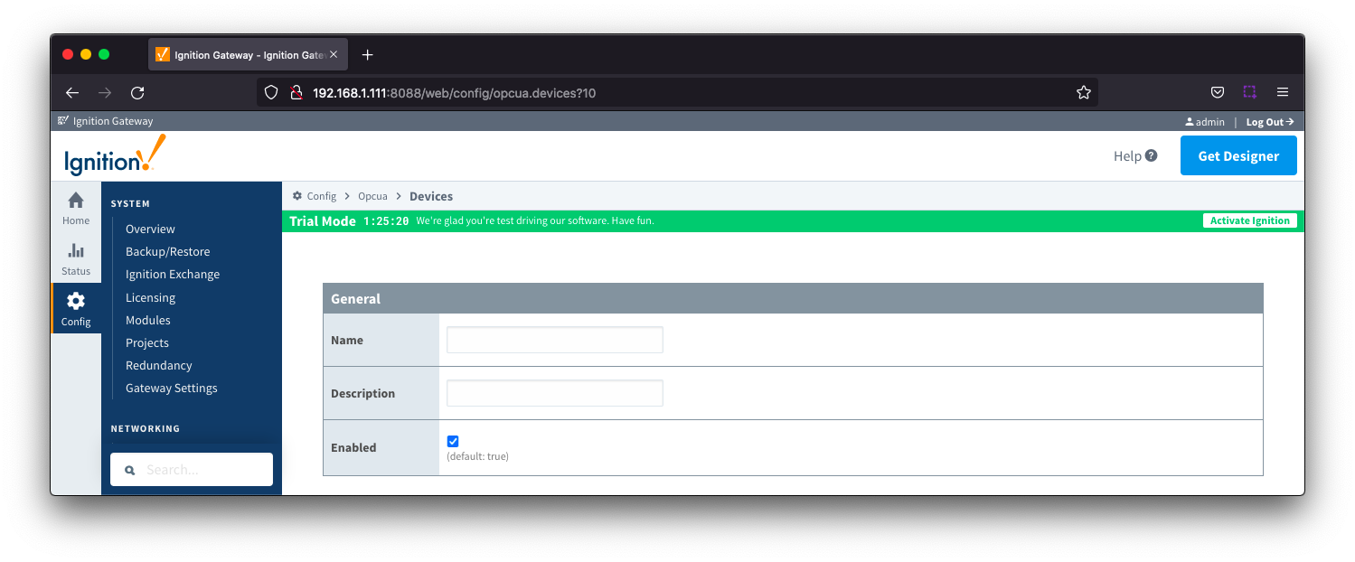
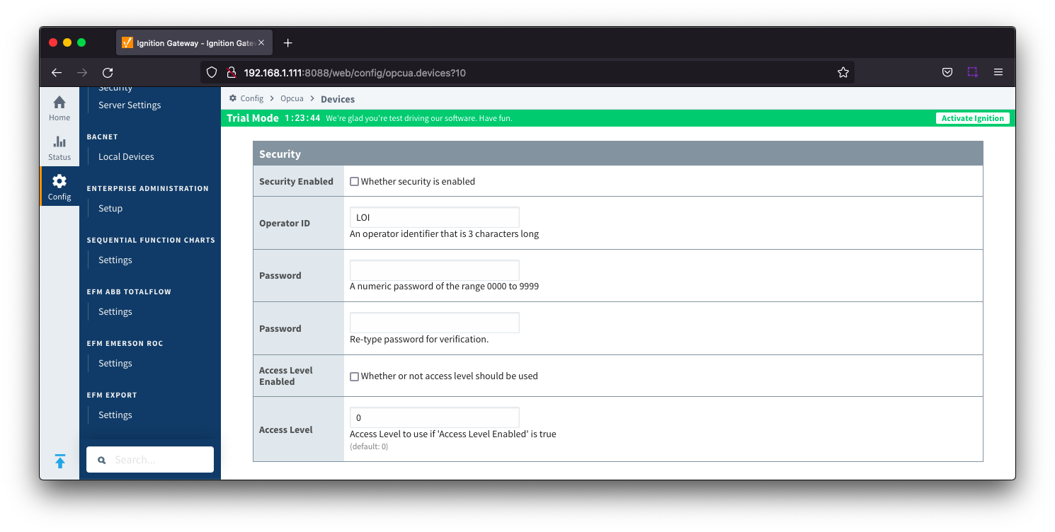
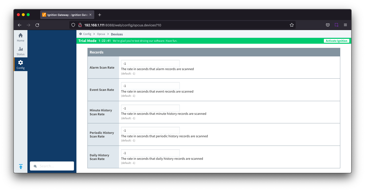
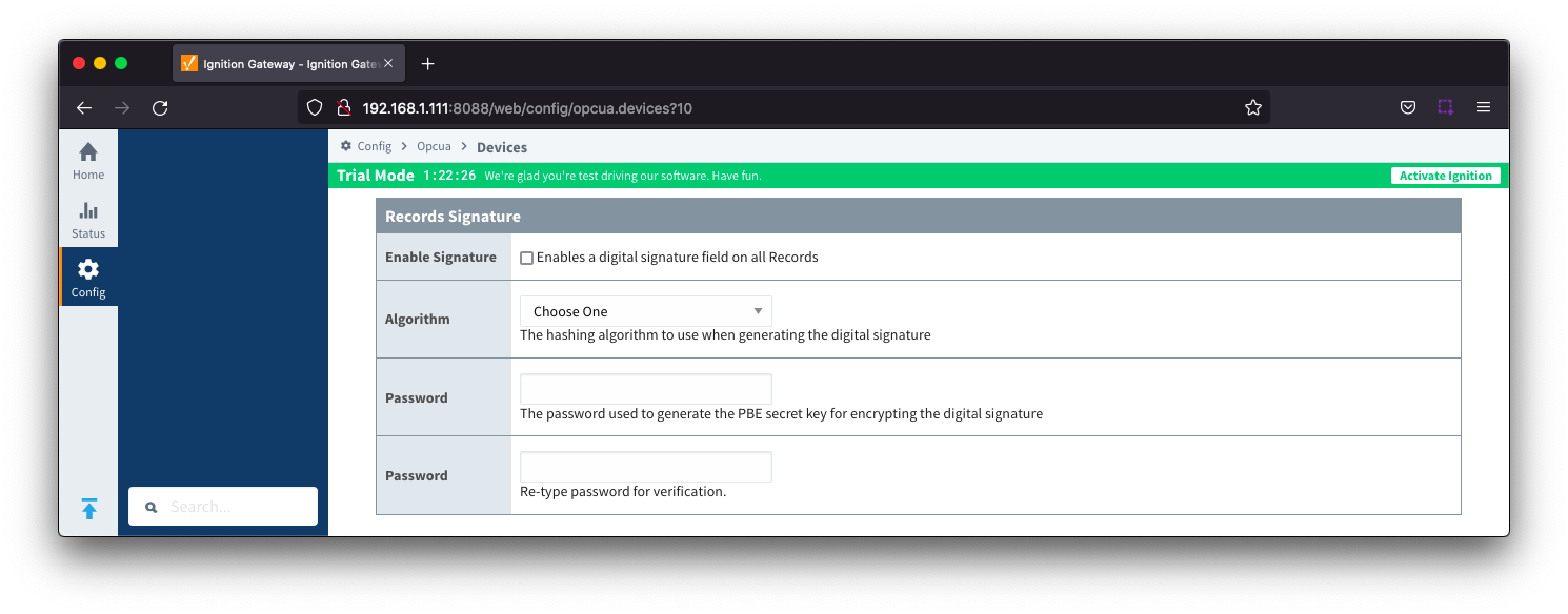
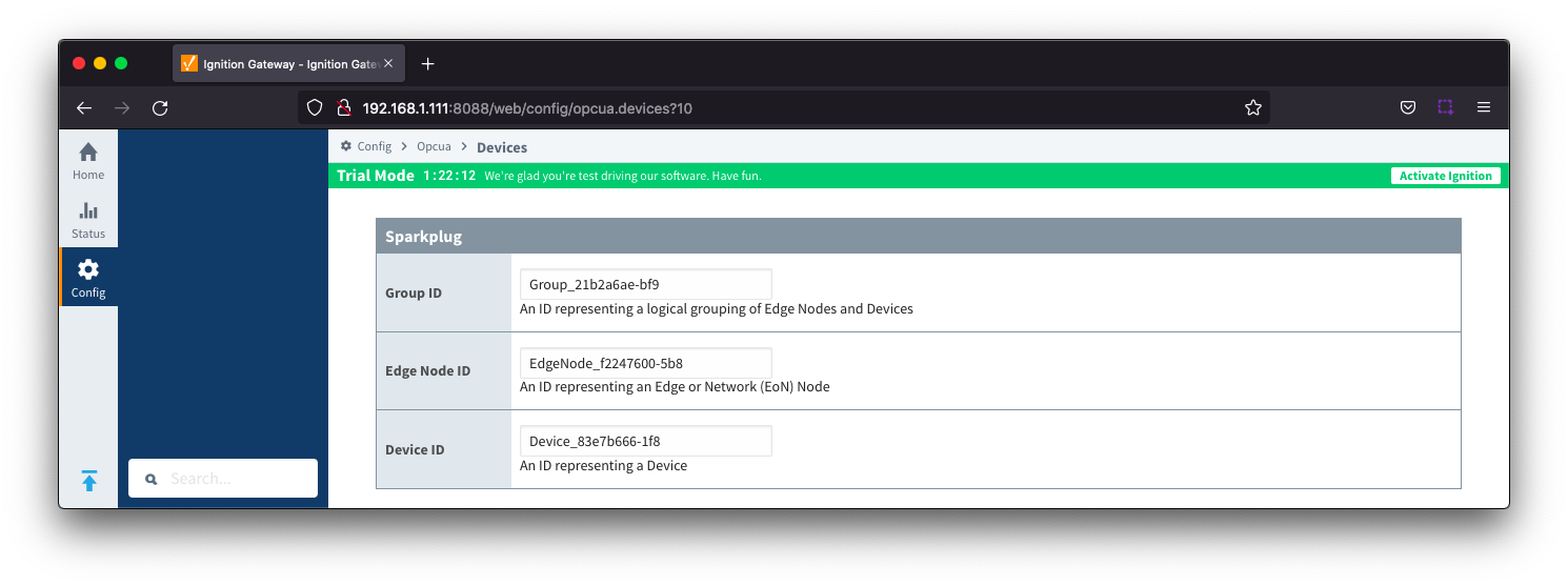
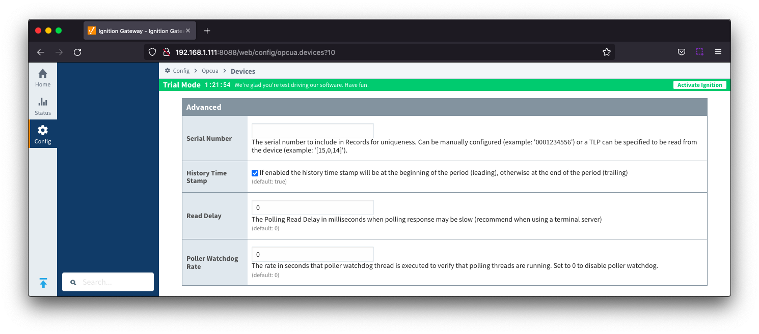
This opens the 'New Device' configuration mage for EFM Emerson ROC Device. The configuration sections available are General, Connectivity, Security, Date/Time, Records, Records Signature, Sparkplug and Advanced Settings.

General

  • Name
    • Device name
  • Description
    • Device description
  • Enabled
    • Checkbox to enable/disable device. Selected by default

Connectivity

  • Protocol Type
    • Specific Protocol Type of the device
      • Options are ROC and ROC_PLUS
  • Hostname
    • Hostname or IP address of the device
  • TCP Port
    • TCP Port of the device
  • Socket Timeout
    • TCP socket operation timeout in seconds. A timeout of zero is interpreted as an infinite timeout. To use the system default, set to -1. Default is 10 seconds.
  • ROC Unit Code
    • Station Address Unit Code of the ROC unit
  • ROC Group Code
    • Station Address Group Code of the ROC unit
  • Host Unit Code
    • Station Address Unit Code of the host (this driver)
  • Host Group Code
    • Station Address Group Code of the host (this driver)
  • Periodic Mapping
  • Configuration Mapping
  • Add All TLP Definitions
    • Checkbox to add all configured TLP definitions. De-selected by default
    • If selected, all TLP definitions configured within the module will be automatically added to this Device configuration.  This is a convenient way to easily add TLP definitions to a Device without having to manually add them after the Device has been initially configured.  If the module contains one or more TLP definitions that are not compatible with the device being configured, leave this option disabled and configure the TLP Definitions manually after the device has been configured. 

Security

  • Security Enabled
    • Checkbox to enabled security on the ROC device. De-selected by default
  • Operator ID
    • A three character operator ID. Default is "Lol"
  • Password
    • A four digit password
  • Access Level Enabled
    • Checkbox to enable Access Level for Operator ID on the ROC device. De-selected by default
  • Access Level
    • The Access Level to use (0-5) if enabled. Default is 0

Date/Time

  • Date Time Offset
    • The date time offset of the ROC clock from the Ignition system running this driver in seconds. Default is 0
  • Sync ROC RTC
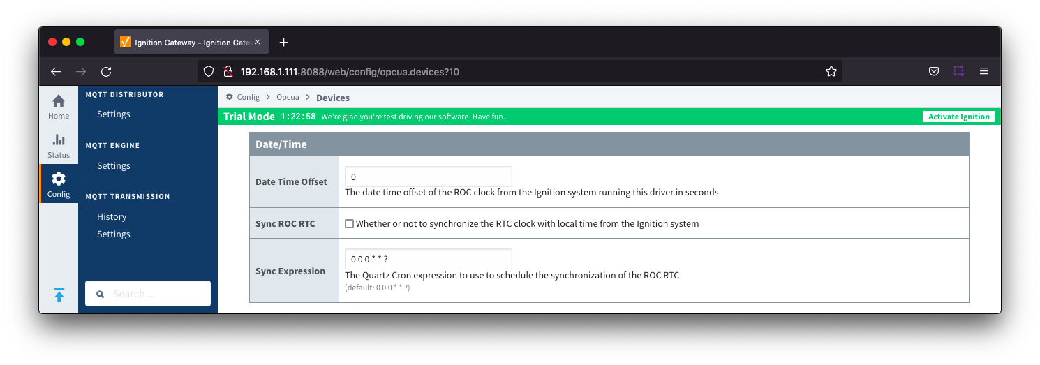
    • Checkbox to synchronize the RTC clock with local time from the Ignition system. De-selected by default

  • Sync Expression
    • The Quartz Cron expression to use to schedule the synchronization of the ROC RTC. Default is "0 0 0 * * ?"

Records

  • Alarm Scan Rate
    • The rate in seconds that alarm records are scanned. Set to -1 to disable alarm scanning. Default is -1
  • Event Scan Rate
    • The rate in seconds that event records are scanned. Set to -1 to disable event scanning. Default is -1
  • Minute History Scan Rate
    • The rate in seconds that minute history records are scanned. Set to -1 to disable minute history scanning. Default is -1
  • Periodic History Scan Rate
    • The rate in seconds that periodic history records are scanned. Set to -1 to disable periodic history scanning. Default is -1
  • Daily History Scan Rate
    • The rate in seconds that daily history records are scanned. Set to -1 to disable daily history scanning. Default is -1

Records Signature

  • Enable Signature
    • Checkbox to enable a digital signature on all Records. De-selected by default
  • Algorithm
    • The hashing algorithm to use when generating the digital signature
    • Options SHA_1,SHA_224, SHA_256, SHA_384 and SHA_512
  • Change Password?
    • Checkbox to allow new password generation. De-selected by default
  • Password
    • Password used to generate the PBE secret key for encrypting the digital signature

Sparkplug

  • Group ID
    • An ID representing a logical grouping of Edge Nodes and Devices
  • Edge Node ID
    • An ID representing an Edge or Network (EoN) Node
  • Device ID
    • An ID representing a Device

Advanced

  • Serial Number
    • The serial number to include in Records for uniqueness. Can be manually configured (example: '0001234556') or a TLP can be specified to be read from the device (example: '[15,0,14]').
  • History Time Stamp
    • Checkbox to enable history time stamp. Selected by default.
    • If enabled the history time stamp will be at the beginning of the period (leading), otherwise at the end of the period (trailing)
  • Read Delay
    • The Polling Read Delay in milliseconds when polling response may be slow (recommend when using a terminal server). Default is 0 milliseconds
  • Poller Watchdog Rate
    • The rate in seconds that the poller watchdog thread is executed to verify polling threads are running. Set to 0 to disable the poller watchdog. Default is 0 seconds.


When all EFM Emerson ROC devices are configured, the Devices page will look as shown below:

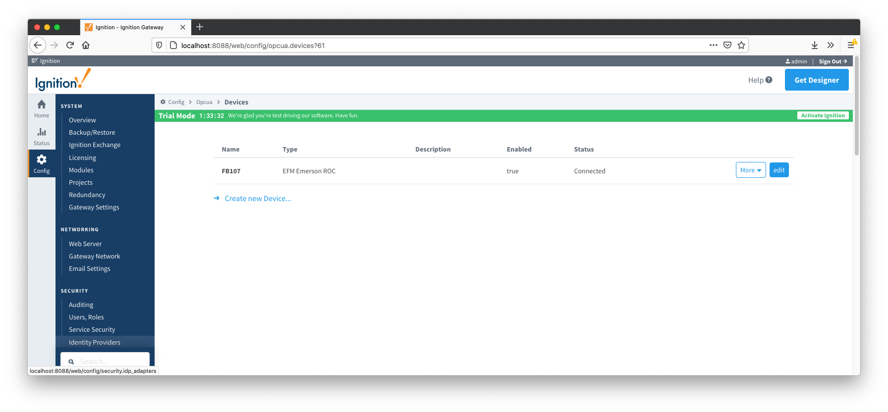
To finish configuring Emerson ROC device, the following three things (as detailed in EFM Emerson ROC Quickstart document) need to be done:

  • Specify TLP Definitions (only if the "Add All TLP Definitions" was not enabled)
  • Provide TLP Templates by importing TLP-template CSV file
  • Configure TLP Poll Groups by importing TLP-poll-group CSV file

When this is done, the 'Devices' configuration page will show the 'Status' of each device set to 'Connected'.

  • No labels