Emerson ROC Device Connection
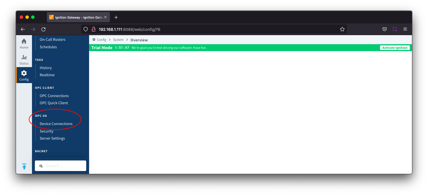
Device connection for Emerson ROC module can be configured via OPC UA configuration. Begin by selecting OPC UA → Device Connections on the left as shown below:
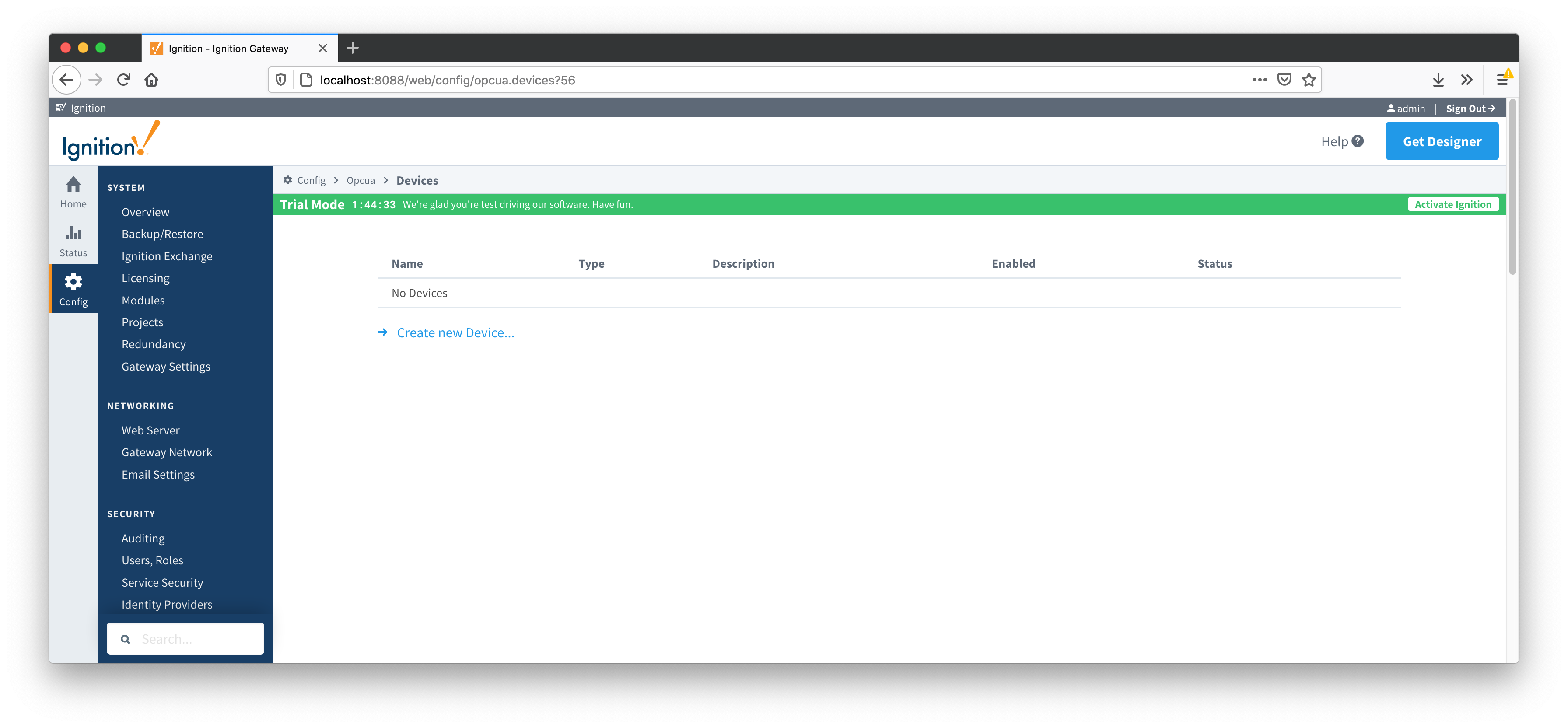
This opens the configuration page as shown below:
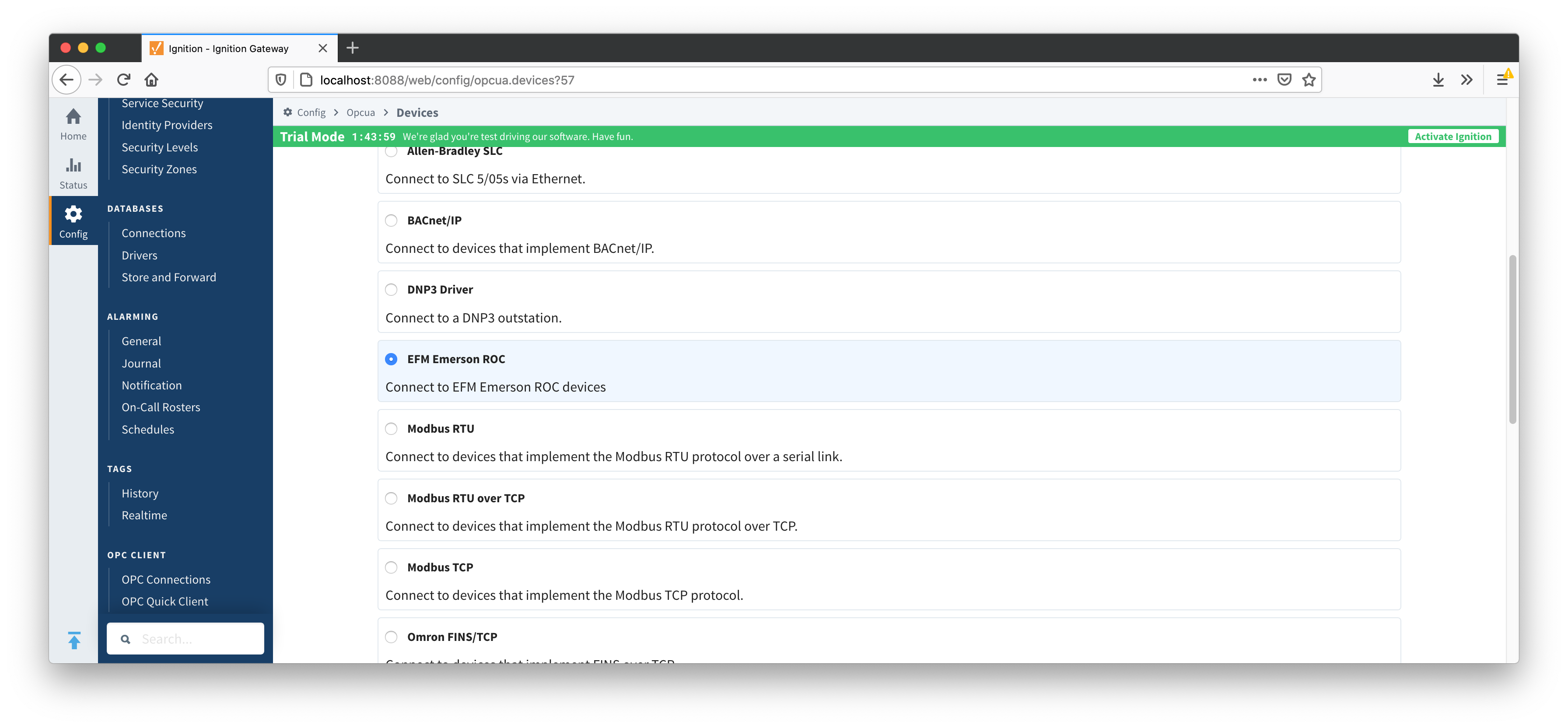
A new Emerson ROC device can be created by following the 'Create new Device...' link and choosing 'EFM Emerson ROC' device as shown below and clicking 'Next' at the bottom of the page.
This opens the 'New Device' configuration page for EFM Emerson ROC Device. The configuration sections available are General, Connectivity, Security, Date/Time, Records, Records Signature, Common File Exchange (CFX), Sparkplug and Advanced Settings.
General
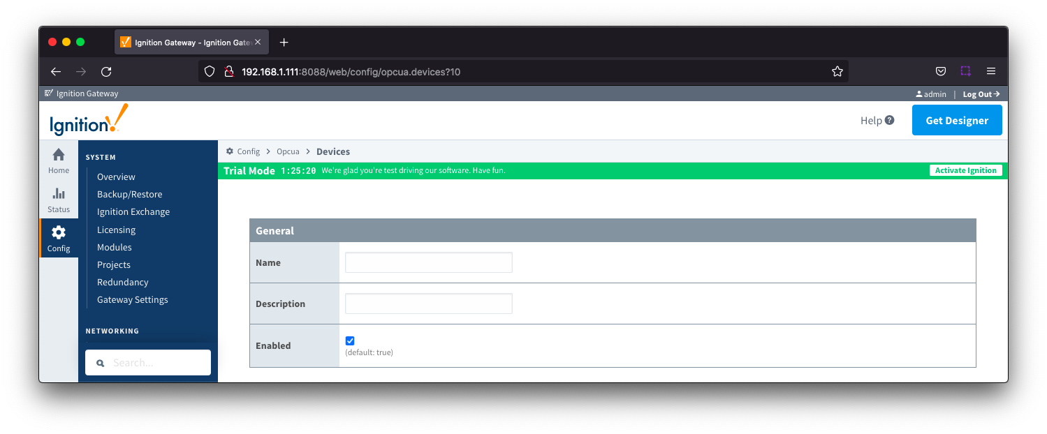
- Name
- Description
- Enabled
- Checkbox to enable/disable device. Selected by default
Connectivity
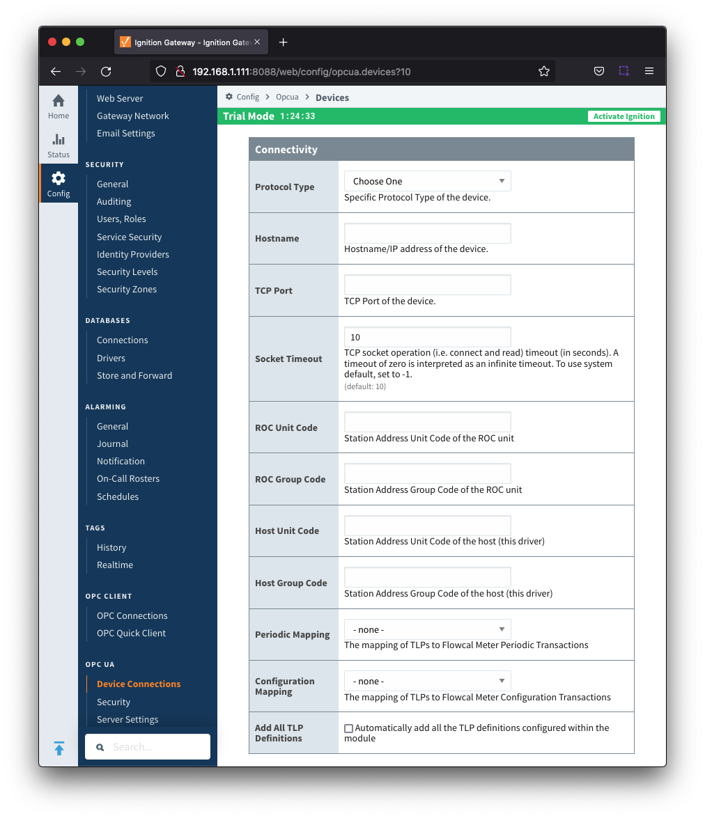
- Protocol Type
- Specific Protocol Type of the device
- Options are ROC and ROC_PLUS
- Hostname
- Hostname or IP address of the device
- TCP Port
- Socket Timeout
- TCP socket operation timeout in seconds. A timeout of zero is interpreted as an infinite timeout. To use the system default, set to -1. Default is 10 seconds.
- ROC Unit Code
- Station Address Unit Code of the ROC unit
- ROC Group Code
- Station Address Group Code of the ROC unit
- Host Unit Code
- Station Address Unit Code of the host (this driver)
- Host Group Code
- Station Address Group Code of the host (this driver)
- Periodic Mapping
- Configuration Mapping
- Add All TLP Definitions
- Checkbox to add all configured TLP definitions. De-selected by default
- If selected, all TLP definitions configured within the module will be automatically added to this Device configuration. This is a convenient way to easily add TLP definitions to a Device without having to manually add them after the Device has been initially configured. If the module contains one or more TLP definitions that are not compatible with the device being configured, leave this option disabled and configure the TLP Definitions manually after the device has been configured.
Security
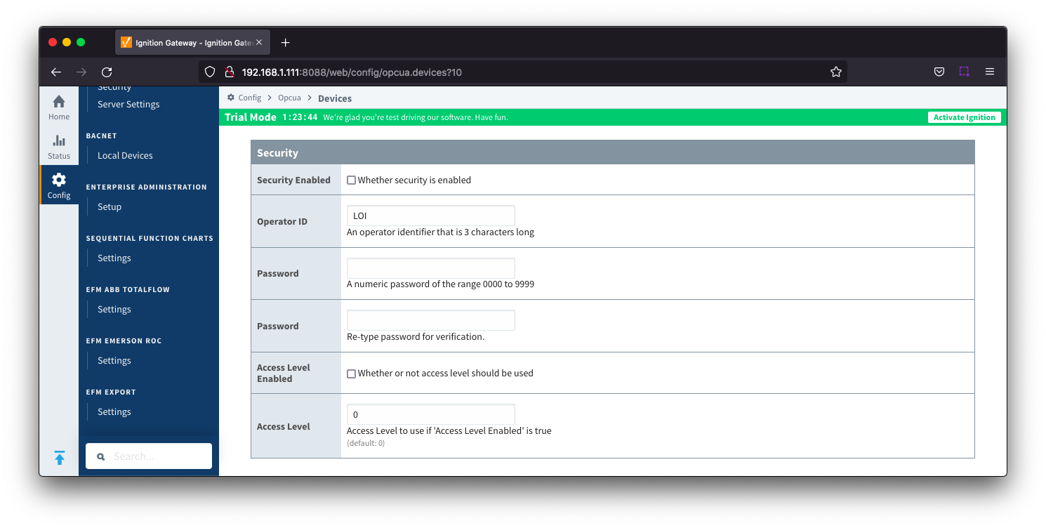
- Security Enabled
- Checkbox to enabled security on the ROC device. De-selected by default
- Operator ID
- A three character operator ID. Default is "Lol"
- Password
- Access Level Enabled
- Checkbox to enable Access Level for Operator ID on the ROC device. De-selected by default
- Access Level
- The Access Level to use (0-5) if enabled. Default is 0
Date/Time
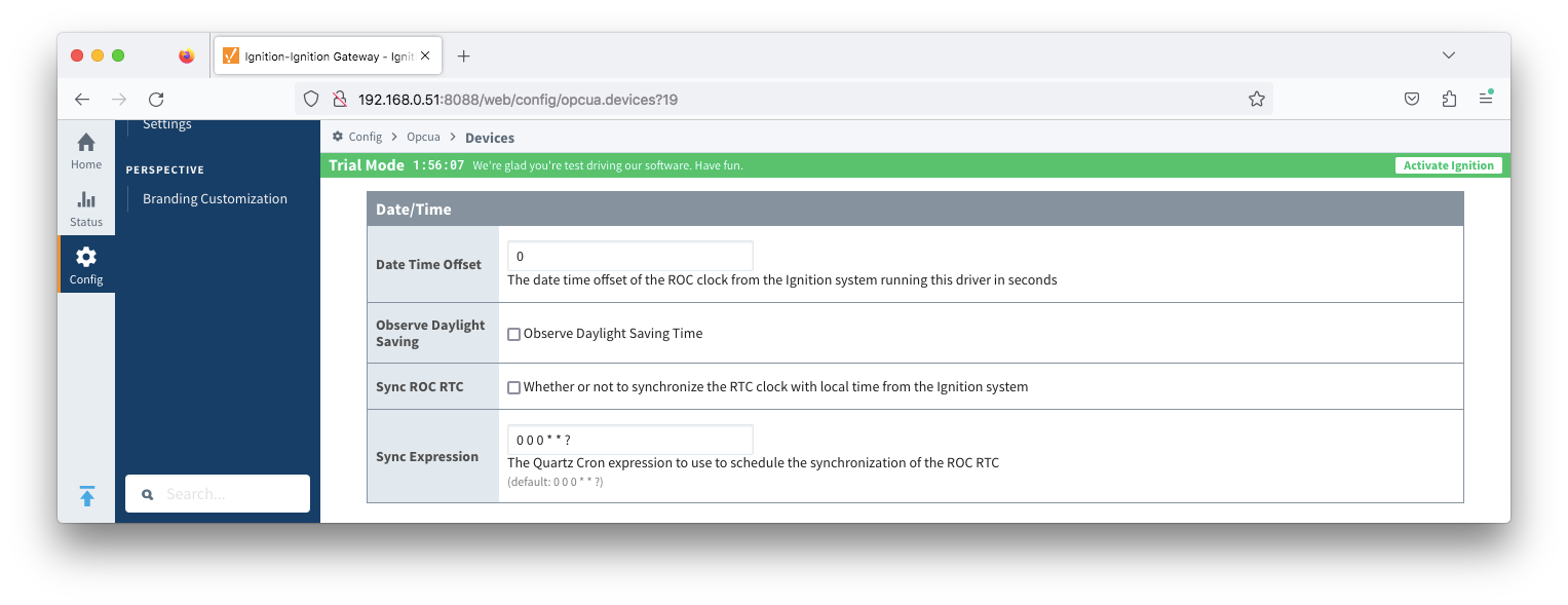
- Date Time Offset
- The offset, in seconds, to add to the Totalflow device clock to convert to UTC. For example, if your Totalflow device is set for CST, you would set this parameter to 7200 to convert any timestamps to UTC.
- Default is 0
- Observe Daylight Saving
- Observe Daylight saving Time
- Sync ROC RTC
- Sync Expression
Records
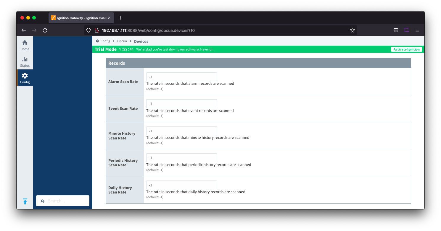
- Alarm Scan Rate
- The rate in seconds that alarm records are scanned. Set to -1 to disable alarm scanning. Default is -1
- Event Scan Rate
- The rate in seconds that event records are scanned. Set to -1 to disable event scanning. Default is -1
- Minute History Scan Rate
- The rate in seconds that minute history records are scanned. Set to -1 to disable minute history scanning. Default is -1
- Periodic History Scan Rate
- The rate in seconds that periodic history records are scanned. Set to -1 to disable periodic history scanning. Default is -1
- Daily History Scan Rate
- The rate in seconds that daily history records are scanned. Set to -1 to disable daily history scanning. Default is -1
Records Signature
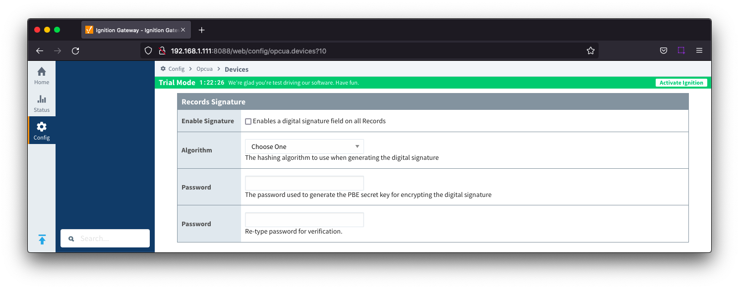
- Enable Signature
- Checkbox to enable a digital signature on all Records. De-selected by default
- Algorithm
- The hashing algorithm to use when generating the digital signature
- Options SHA_1,SHA_224, SHA_256, SHA_384 and SHA_512
- Change Password?
- Checkbox to allow new password generation. De-selected by default
- Password
- Password used to generate the PBE secret key for encrypting the digital signature
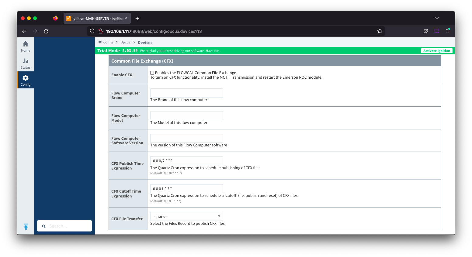
- Enable CFX
- Enables/disables the FLOWCAL Common File Exchange.
- When enabled, CFX and associated CFX.MD5 files will be created with a naming convention of meterid.cfx and meter_id.cfx.md5. New Alarm, Event and PeriodicHistory records will be added to the file.
- Files will be stored on the Ignition instance where the driver is installed under this filepath <ignition folder>/data/modules/com.cirrus-link/efmemersonroc/devices/<device id>/meters/<meter id>/
- Flow Computer Brand
- Free form text field to identify flow computer brand included in the CFX file. Limit of 20 characters
- Flow Computer Model
- Free form text field to identify flow computer model included in the CFX file. Limit of 20 characters
- Flow Computer Software Version
- Free form text field to identify the flow computer software version included in the CFX file. Limit of 20 characters
- CFX Publish Time Expression
- This parameter is used when publishing the files with MQTT Transmission and defines the Quartz Cron expression used to schedule publishing of CFX files
- This will trigger the CFX file to be copied to the "Publish File Path" configured for the MQTT Transmission File record selected in the "CFX File Transfer" parameter. This file can then be picked up and published automatically by MQTT Transmission and the CFX file remains in the source folder (under ~/data/modules) to be maintained.
- Default is "0 0 0/2 * * ?". Reference the Cron Trigger Tutorial for details on this expression and Cron Expression Generator for configuring this expression
- This expression can be empty to use the CFX Cutoff Time Expression only
- CFX Cutoff Time Expression
- This parameter is used when publishing the files with MQTT Transmission and defines the Quartz Cron expression used to schedule publishing of CFX files
- This will trigger the CFX file to be moved to the "Publish File Path" configured for the MQTT Transmission File record select in the "CFX File Transfer" parameter. This file can then be picked up and published automatically by MQTT Transmission and the EFM driver notified that it needs to collect meter configuration and generate a new set of CFX files.
- Default is "0 0 0 L * ? *". Reference the Cron Trigger Tutorial for details on this expression and Cron Expression Generator for configuring this expression
- The expression should never be empty to prevent the CFX file from becoming to large to publish
- CFX File Transfer
- This parameter is used when publishing CFX files with MQTT Transmission and provides a dropdown containing all the File definitions from MQTT Transmission.
- A MQTT Transmission File definition defines a location for all the control tags required to publish files including the "Publish File Path".
- Default is none. CFX files will be created and maintained but will not be published. New Alarm, Event and PeriodicHistory records will be added to the file until the device connection is removed.
Sparkplug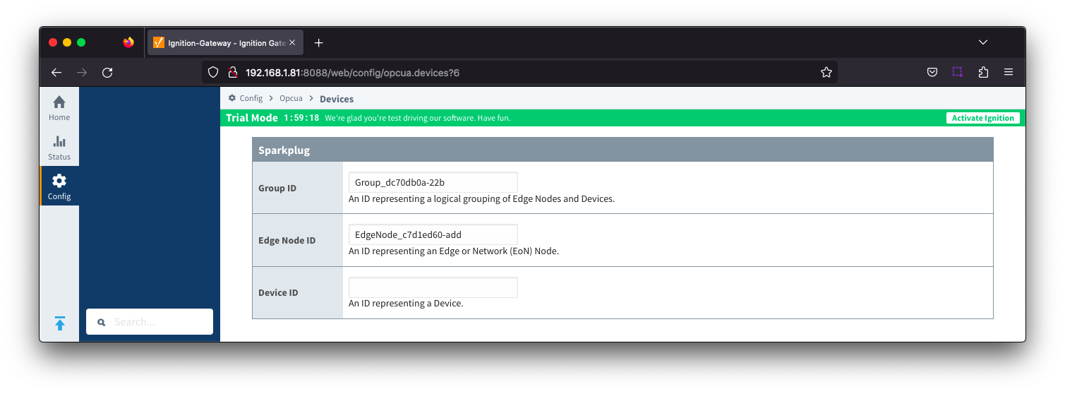
To publish Records such as Alarms, Events or History, a configured MQTT Transmission Transmitter is used.
If you do not have a Transmitter configured, create an MQTT Transmitter and set the Sparkplug Settings to the unique Group and Edge Node ID values generated by the Device Connection configuration.
If a Transmitter already exists, for example to publish the polled/live data, you can edit the Group and Edge Node IDs to match the existing Sparkplug Edge Node created by the Transmitter.
- Group ID
- An ID representing a logical grouping of Edge Nodes and Devices
- Edge Node ID
- An ID representing an Edge or Network (EoN) Node
- Device ID
- An ID representing a Device
Advanced
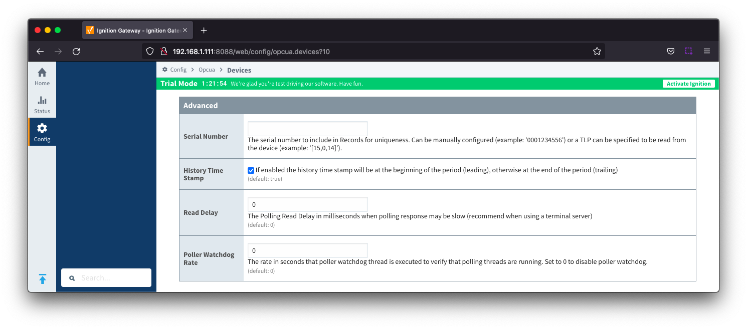
- Serial Number
- The serial number to include in Records for uniqueness. Can be manually configured (example: '0001234556') or a TLP can be specified to be read from the device (example: '[15,0,14]').
- History Time Stamp
- Checkbox to enable history time stamp. Selected by default.
- If enabled the history time stamp will be at the beginning of the period (leading), otherwise at the end of the period (trailing)
- Read Delay
- The Polling Read Delay in milliseconds when polling response may be slow (recommend when using a terminal server). Default is 0 milliseconds
- Poller Watchdog Rate
- The rate in seconds that the poller watchdog thread is executed to verify polling threads are running. Set to 0 to disable the poller watchdog. Default is 0 seconds.
With the device now established you must configure the specific global TLP Definitions associated with the device, create TLP Templates and TLP Poll Groups to use.
- TLP Definitions provide human readable context to each TLP as well as the datatype and data length. The TLP Definition csv files are uploaded through the Emerson ROC Driver configuration.
- TLP Templates are groupings of T and P values which should be polled together.
- TLP Poll Groups attach an L value to a TLP Template along with a Tag Folder Path which defines where the polled data will be represented under the device in the Ignition OPC UA Server
Specifying TLP Definitions for a Device
With the device now established the specific global TLP templates that are appropriate for this device must be associated with it. Do so by clicking the 'More' drop-down button and selecting 'TLP Definitions' as shown below.

You should now see an empty list of TLP definitions (unless you used the "Add All TLP Definitions" setting).

Click the 'Add Row' link that is shown below. This will show a new TLP definition with a select box to allow you to select which global TLP definition you want to associate with this device. Add as many as are appropriate for your device as shown below.
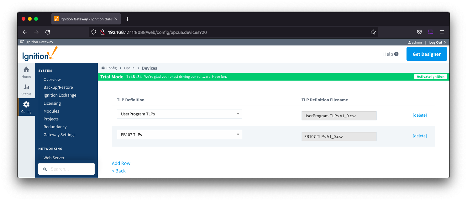
When complete, save the list and you will be taken back to the Devices list.
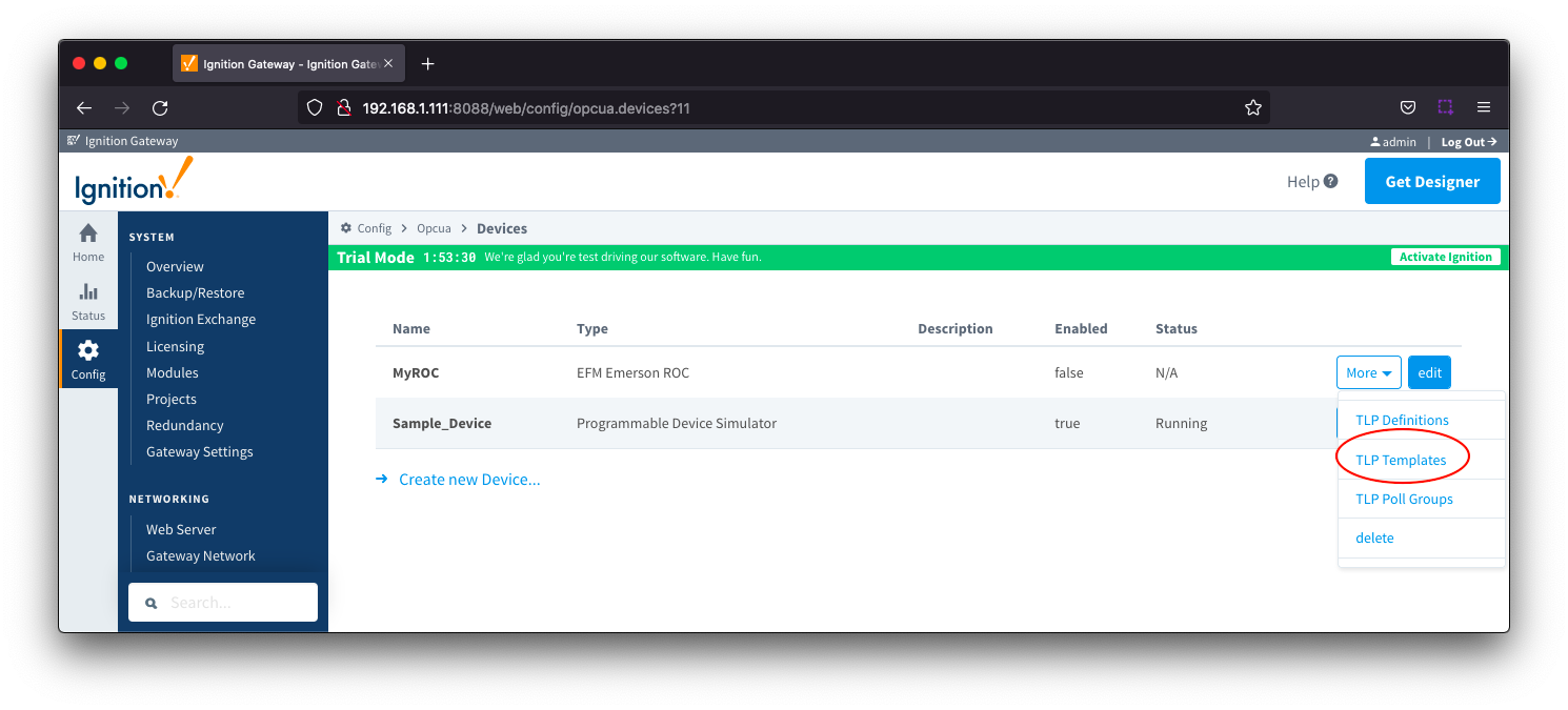
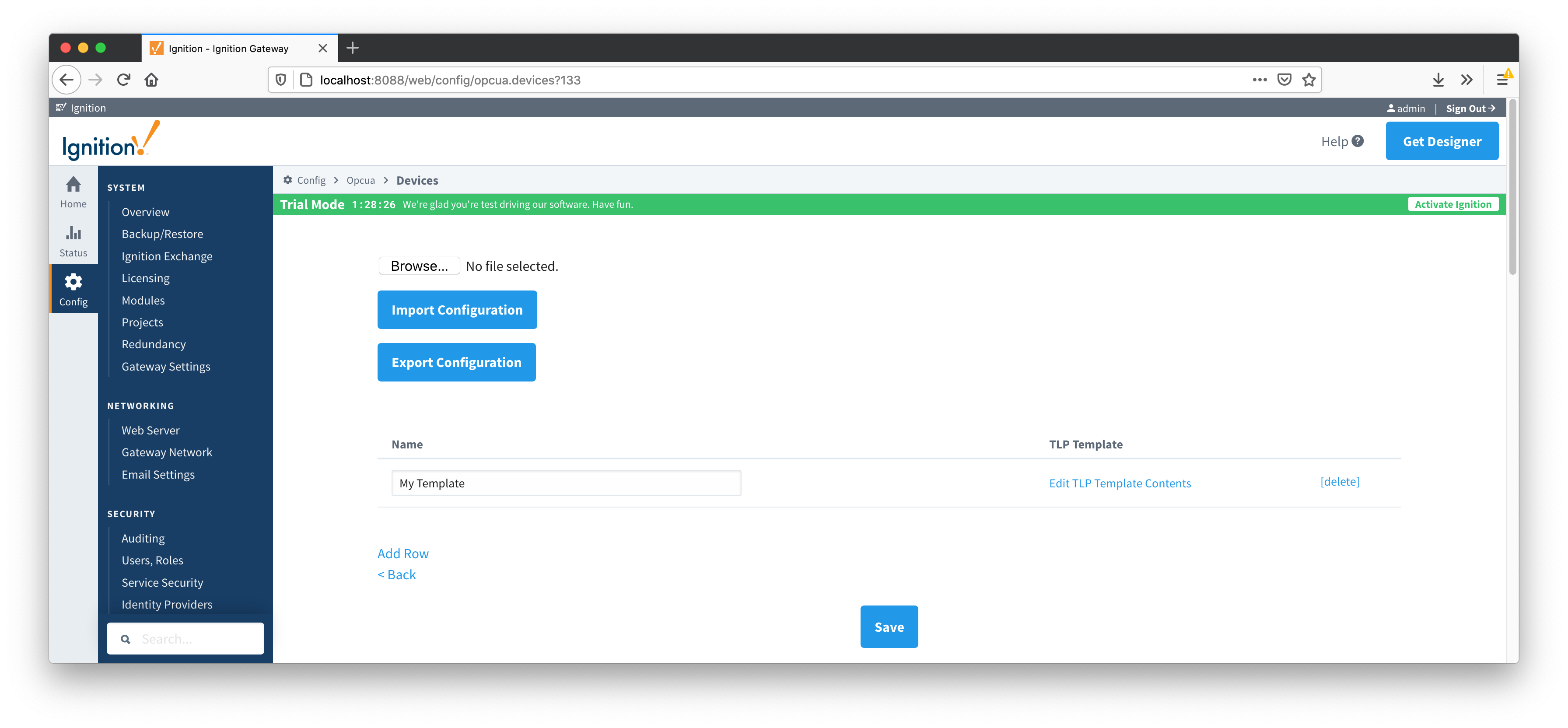
Creating TLP Templates for a Device
With the TLP definitions now defined for this device we can create some TLP templates to allow creation of TLP poll groups. To create a TLP template, click on the 'More' drop-down menu and select 'TLP Templates' as shown below.
To add a TLP template, click the 'Add Row' link shown below.
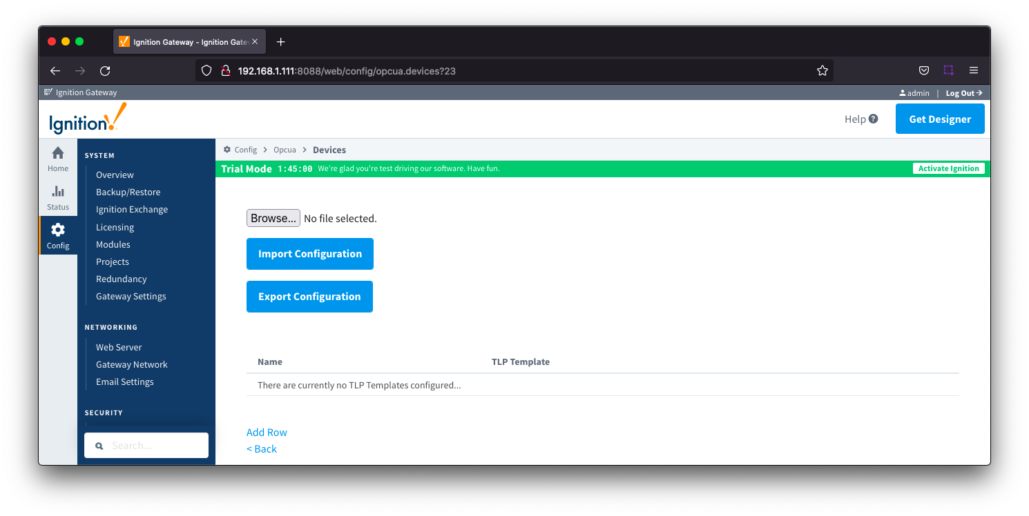
Give the new TLP template a name that makes sense and then click the 'Edit TLP Template Contents' link next to the name field shown below.

Add your new TLPs by clicking the 'Add Row' link shown below.
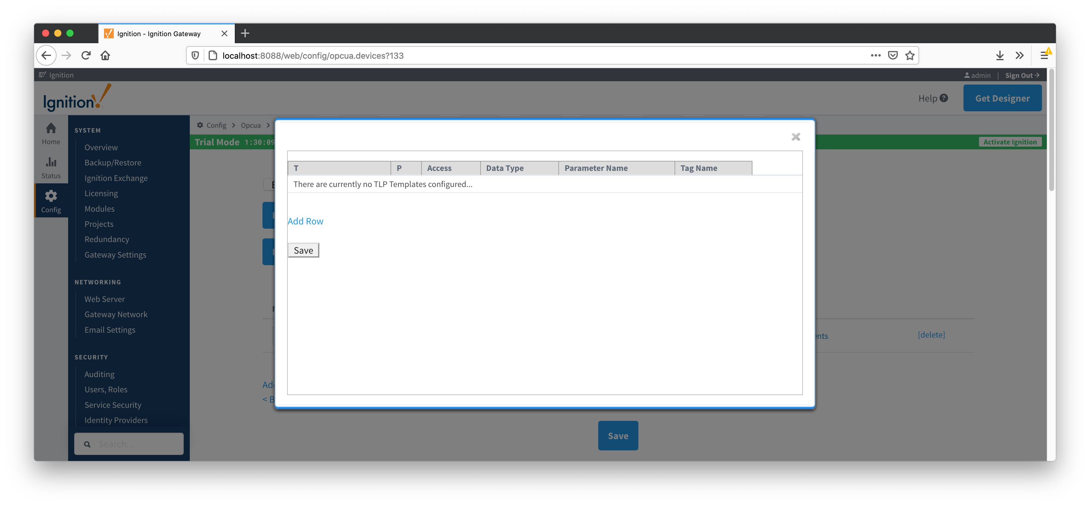
Note there are six fields available for each row of which only three can be modified. These are:
- T
- The 'T' parameter of the TLP
- P
- The 'P' parameter of the TLP
- Tag Name
- The tag name that will show up in Ignition for this TLP.
- The default value comes from 'Parameter Abbreviation' of the global TLP definition CSV file. It can be changed here to any value.
The remaining fields are defined in the global TLP definition CSV file and cannot be modified here:
- Access
- The access for this value - either RO for 'read only' or RW for 'read/write'
- Data Type
- The data type for this TLP
- Parameter Name
- The descriptive name of this TLP
The TLPs available to be added are based on the TLP definitions that have been made available to this specific device. Add as many templates that make sense to be grouped together in a logical group. When complete you should see something similar to what is shown below. Click the 'Save' button.

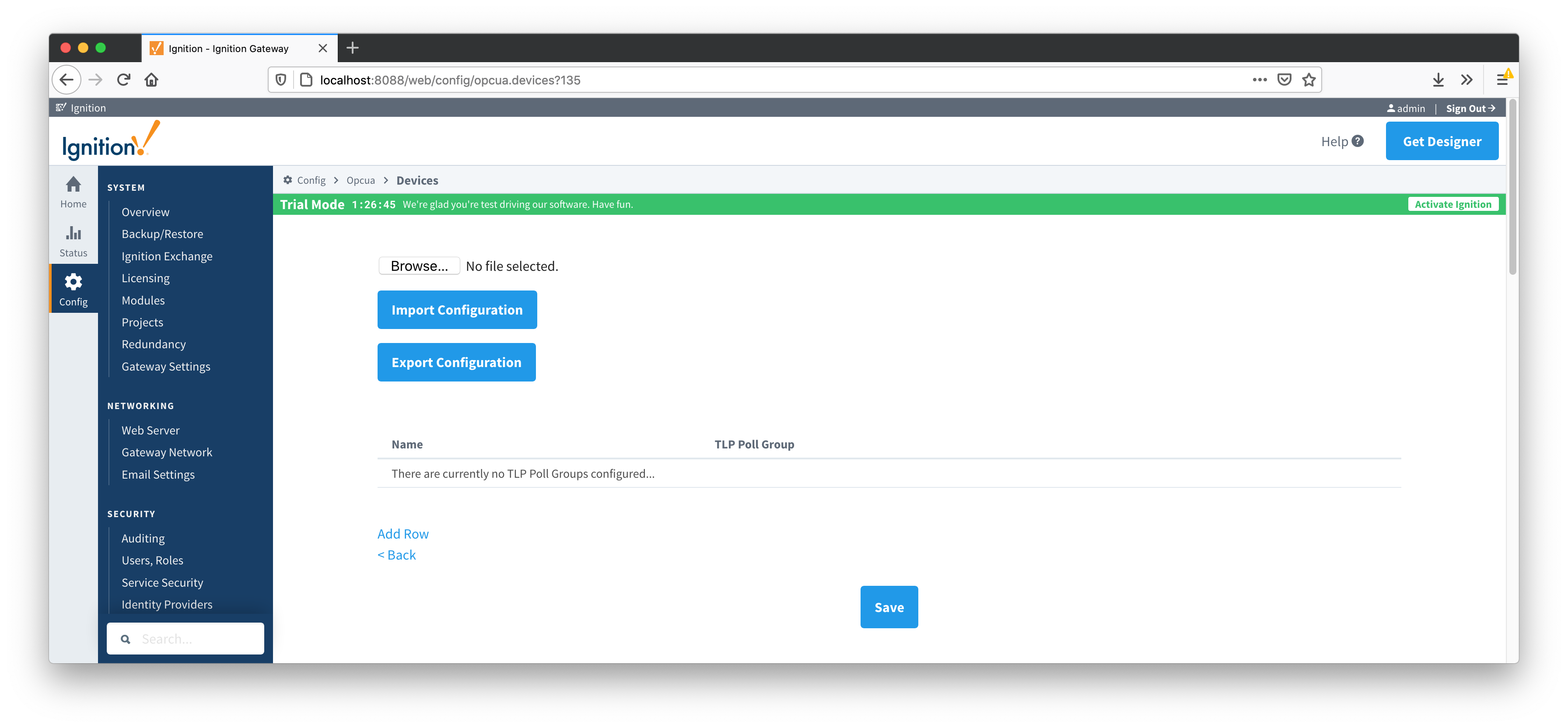
Creating TLP Poll Groups for a Device
With TLP templates already defined you can now create TLP poll groups which will poll a group of TLPs via a TLP template at a specific logical number at a specified rate.
Do so by selecting 'TLP Poll Groups' via the 'More' drop-down as shown below.

To add a TLP poll group, click the 'Add Row' link shown below.
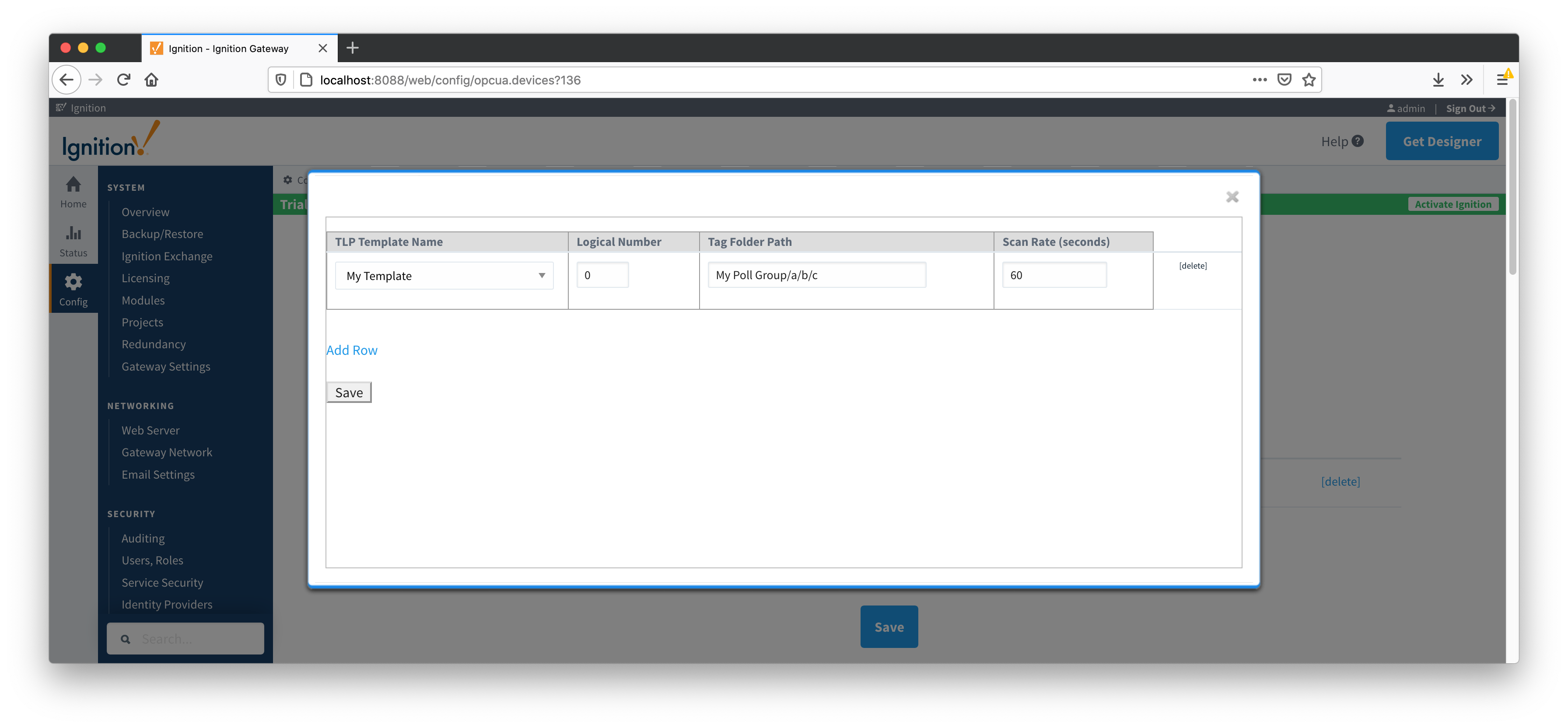
Now you can give the new TLP poll group a name that makes sense. Then click the 'Edit TLP Poll Group Contents' link next to the name field shown below.

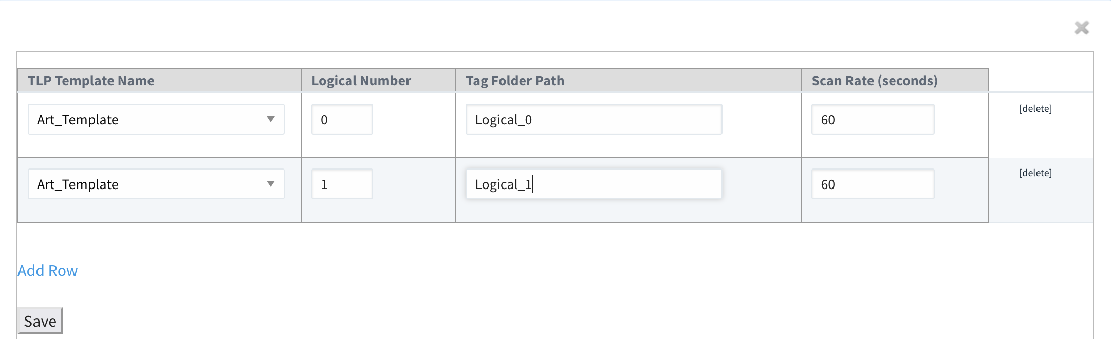
At this point you can create a poll group using one or more TLP templates as shown below. The parameters that must be set here are:
- TLP Template Name
- The TLP template to use for this poll group
- The TLP templates available to choose from are based on the TLP templates defined for this device
- Logical Number
- The 'L' parameter of this TLP template.
- Tag Folder Path
- The Tag Folder Path where the polled data will be represented under the device in the Ignition OPC UA Server
- Scan Rate
- The rate (in seconds) at which to poll all of the TLPs in this TLP template.
When complete, click the 'Save' button to save the TLP poll group.
Create as many TLP poll groups as you'd like as shown below. Once complete, click the 'Save' button at the bottom of the page below.
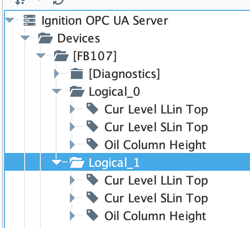
Once the poll group has been saved, the Device Connection Status will change to Polling and the tags will be shown in Ignition similar to below: