Abstract
This tutorial details how to connect existing Modbus RTU devices over a serial network into the Ignition Modbus TCP driver using a third party serial to ethernet gateway.
For this tutorial we are using three CLICK PLCs connected over RS-485 and an MGate MB3170/MB3270 Series Gateway from Moxa which is readily available for purchase from Amazon.
MGate Topology and serial connections
The image below shows an example of how Modbus RTU Devices would be connected through the Moxa gateway.
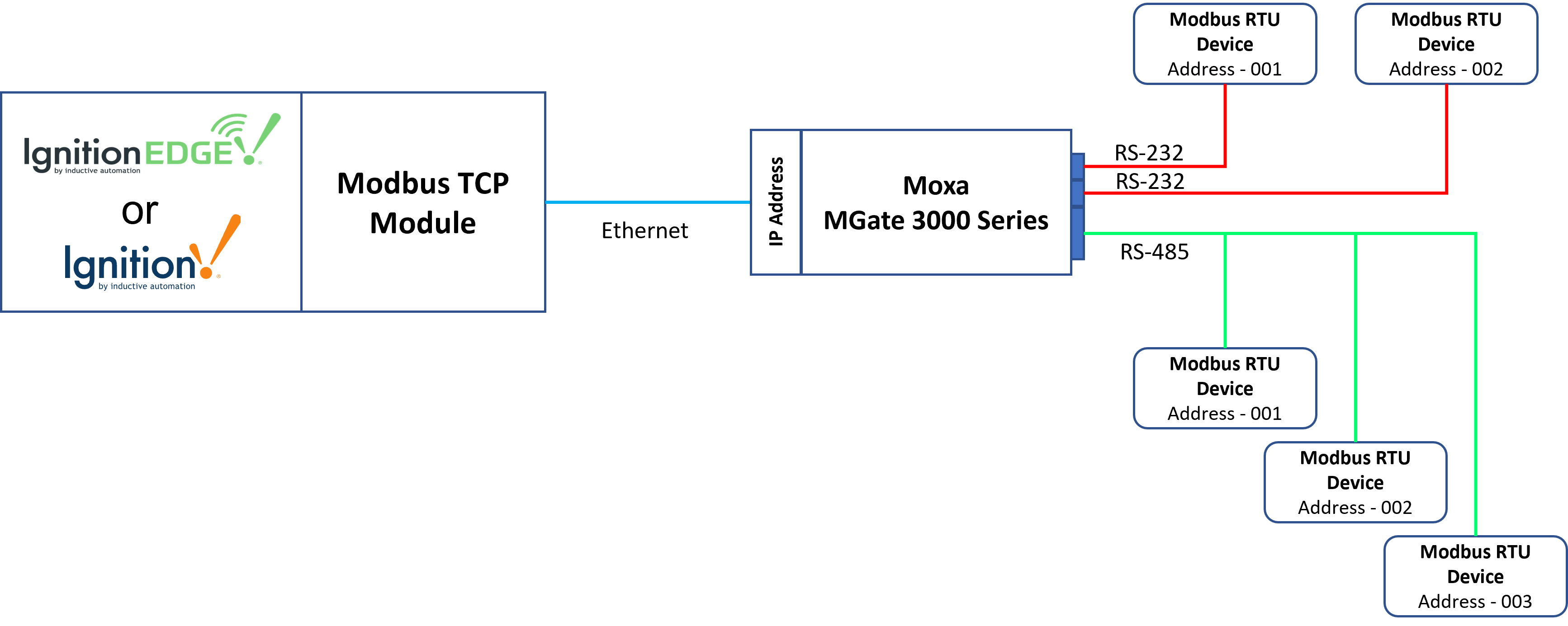
The gateway uses male DB9 serial ports to connect to the Modbus RTU or ASCII devices.
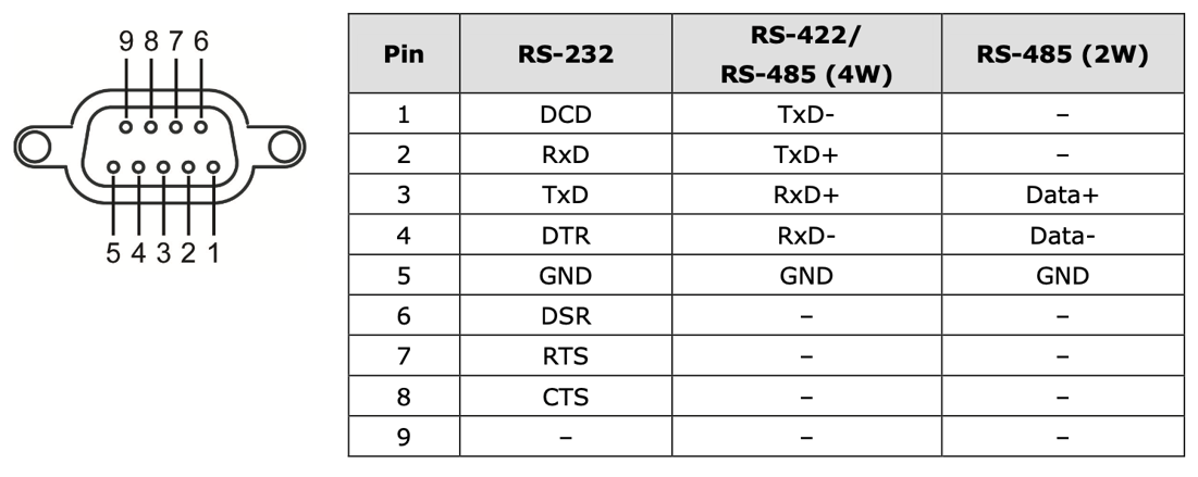
Each port supports three serial interfaces: RS-232, RS-422 and RS-485 (both 2 and 4 wire) with the pinout shown below:
MGate Configuration
Initial Configuration Access
Moxa provide a Windows based utility that can be used to connect to the MGate and aid in configuring the unit. But the MGate also provides a native web UI that provides the same functionality from any operating system. Out of the box the MGate will have the following default TCP/IP address and default Account and Passwords:
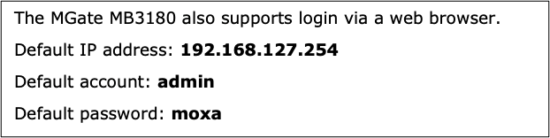
Temporarily set your computer’s Ethernet domain to the 192.168.127.xxx domain. Once you have done that, open a web browser and browse to http://192.168.127.254. That will result in the following web page being displayed:

After you enter the default admin/moxa credentials you will be prompted to enter a new password.
Setting a Static IP Address
Once you have logged into the MGate unit, navigate to the “Network Parameter” tab within the web UI. The MGate unit provides for both DCHP as well as STATIC IP settings. Because we want the MGate to reliably appear at a known IP address after things like power outages and resets, it is best to configure the device with a known STATIC IP address.
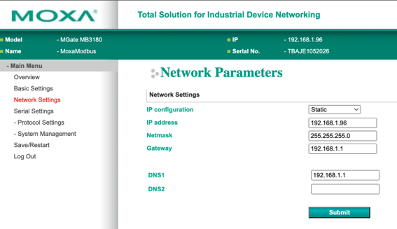
- Under the “IP Configuration” drop down in the Web UI, select “Static”.
- Enter a Static IP address that makes sense in your network topology. In this example, we have used 192.168.1.96
- Set the Netmask to what makes sense in your network topology (typically this will be a 255.255.255.0 setting)
- Finally, setup a Gateway IP address. Note, in typical use cases routing thru a Gateway will not be used.
- The DNS1 entry can default to the Gateway IP set above in most use cases.
- Once all of the entries have been made, click on the “Submit” button to activate these settings.
Configuring the Serial Port
The purpose of the Moxa MGate device is to provide that translation layer between the more modern Modbus TCP layer of the protocol to the original Modbus RTU protocol that was designed to work over legacy RS-232/RS-485 serial networks.
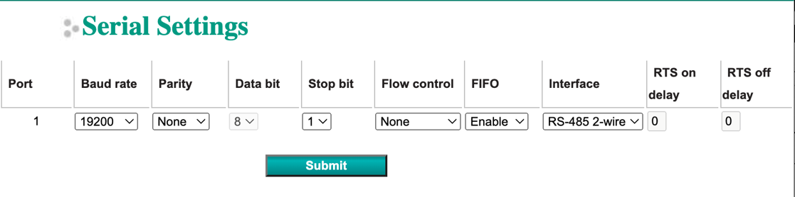
The next step is to configure is the type of serial port connection (RS-232, RS-485 2 Wire, RS-485 4 wire, or RS-422) and the serial port UART parameters of baud rate, data bits, stop bits, and parity. Click on the left ”Serial Settings” tab to bring up this configuration page:
Configuring the Modbus TCP Parameters
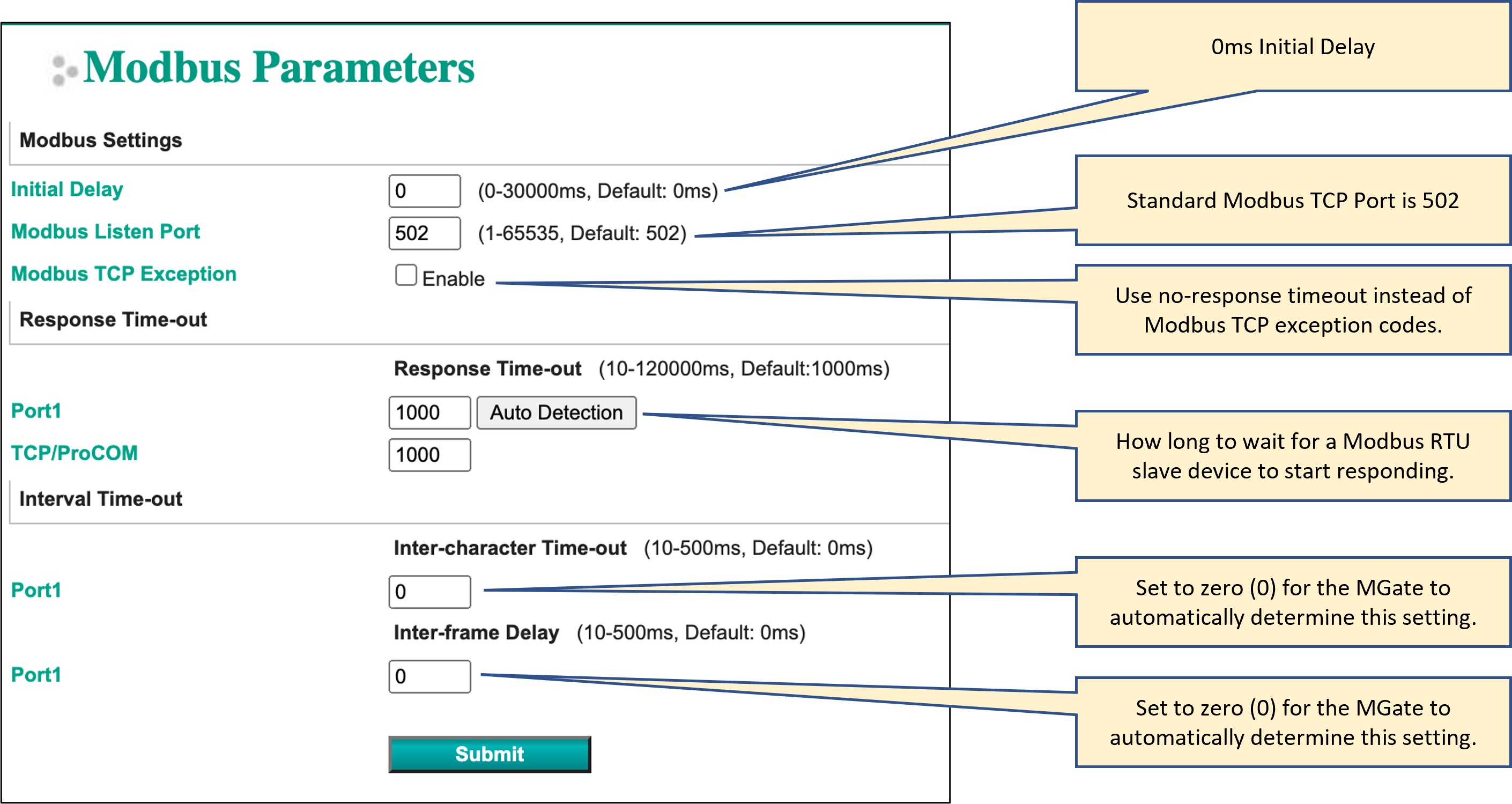
The next step is to configure the Modbus TCP parameters of the MGate. This includes the Initial Delay, the TCP Port number that Modbus TCP will be listening on, the Response Time-out of any Modbus RTU slave devices attached to the MGate, and the Inter-character Time-out and Inter-frame Delay.
Setup the Modbus Parameters as shown below:
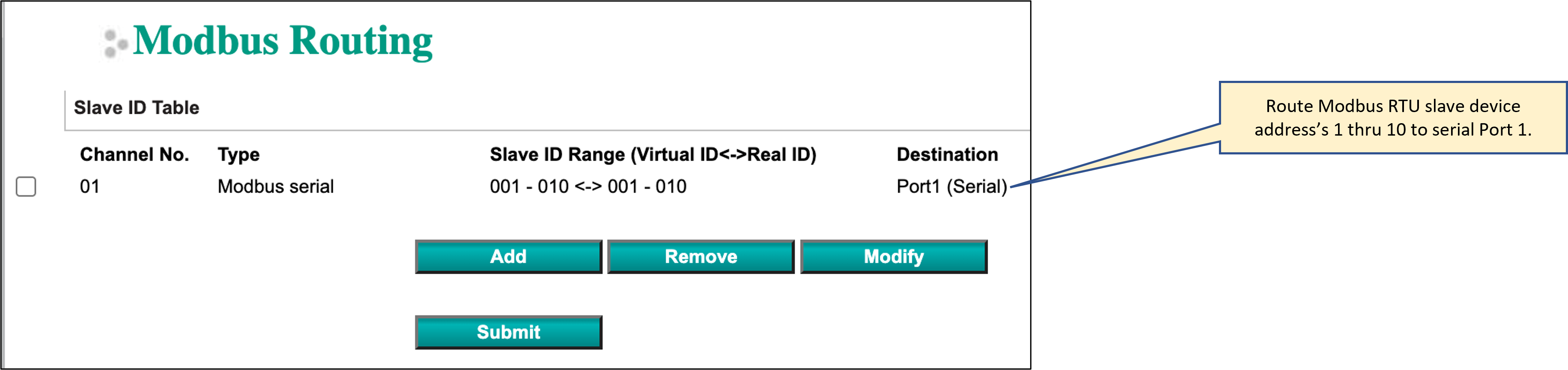
Configuring the Modbus Routing
The last item to configure on the MGate is the Modbus Routing. This informs the MGate which serial port to use for a range of Modbus RTU slave device addresses. For this example, we’re using an MGate MB3180 which only has a single serial port, so the routing is simple. For other MGate units with multiple serial ports this would inform the MGate which serial port to use for associated Modbus RTU slave device addresses.
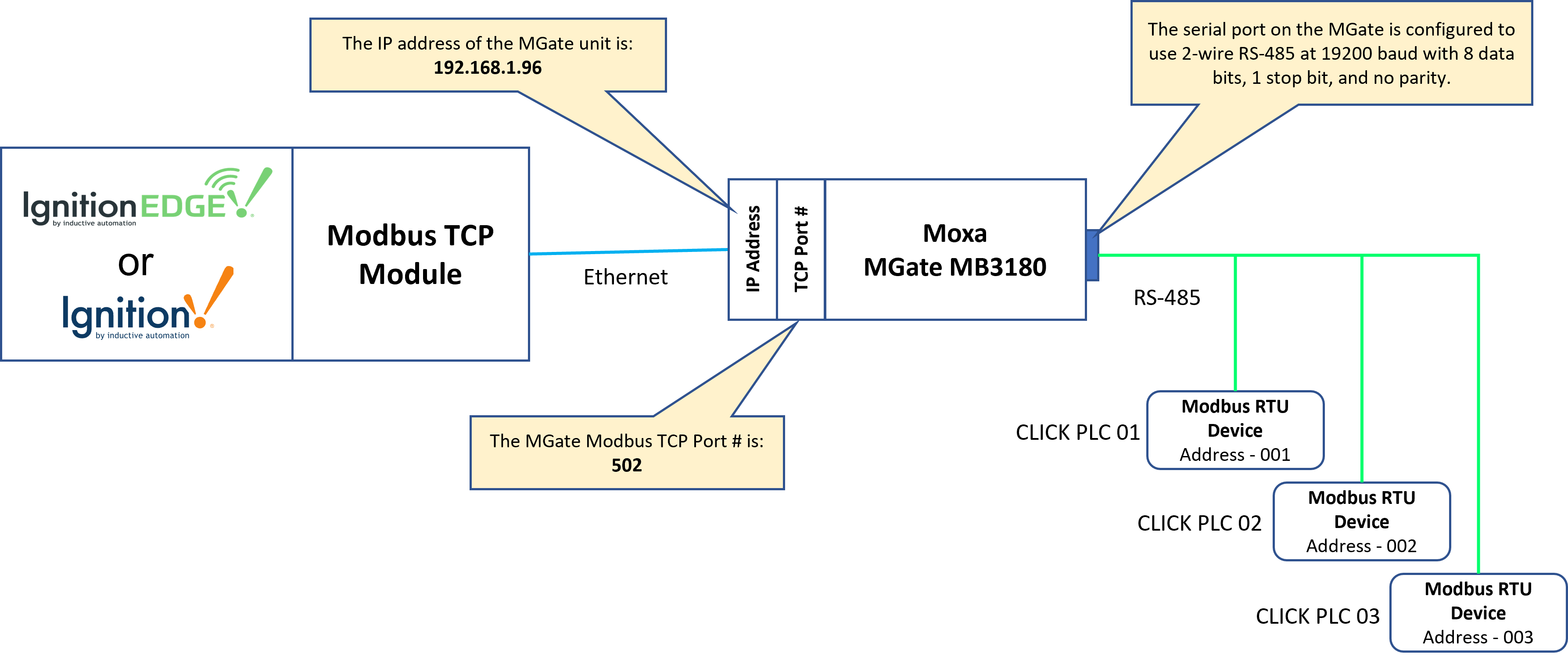
Once the configuration steps have been completed, the resulting network topology is shown below:
Configuring the Ignition Modbus TCP Driver
Now that the MGate unit is setup and providing a Modbus TCP to Modbus RTU RS-485 multi-drop serial network, we’ll proceed to setting up the Modbus TCP driver in Ignition to take advantage of this network.
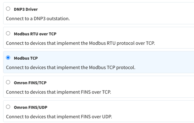
In Ignition, from the left hand menu bar, select Config > OPC UA > Device Connections > Create new Device... and select the “Modbus TCP” driver from the list of protocols:
This will display the Modbus TCP configuration page. Setup the configuration as shown below:
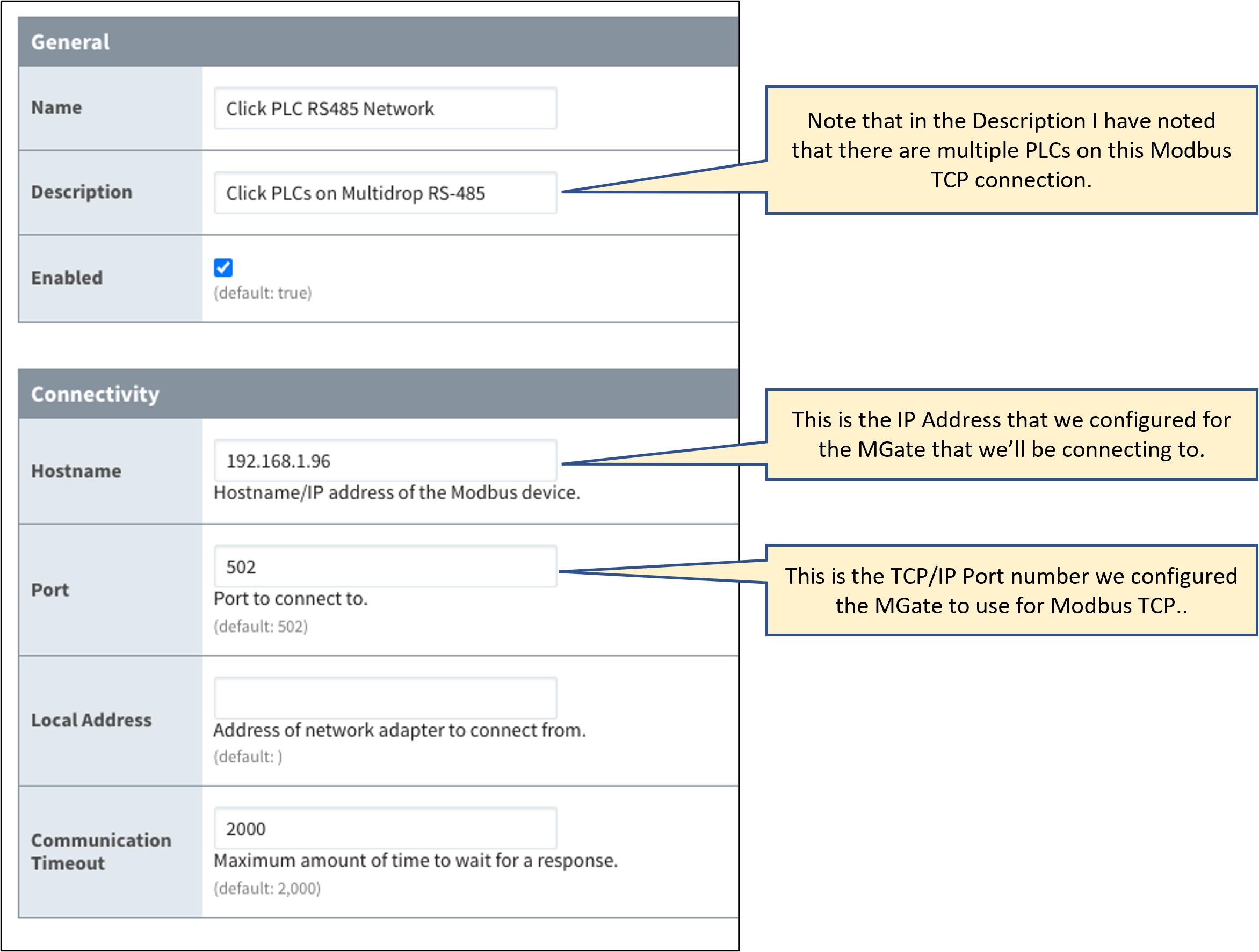
Once you save the configuration for the Modbus TCP connection and everything is setup properly on the MGate you should see the “Status” of the connection change to “Connected”.

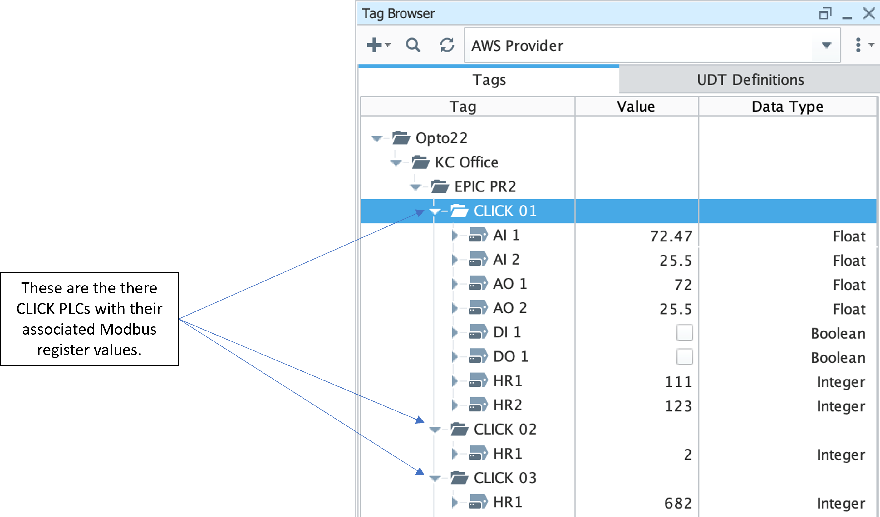
In Ignition Designer, create a tag tree under your required Tag Provider for each of the CLICK Modbus PLCs. Now we can start to add OPC tags under each PLC folder and associate with the appropriate Modbus PLC and Register.
When you configure Ignition tags that pull Modbus register information from any of the Modbus RTU devices connected to the MGate unit, you will need to specify the Modbus RTU Address, Modbus Data Type and Modbus Register Address by appending to the OPC Server Path in the OPC Item Path.
The format is [OPCServerPath]X.YYYZZZZZ where:
X = Modbus RTU Address
YYY = Modbus Datatype Designator
ZZZZZ = Modbus Register Address
For example, with the OPC UA Server Path as ns=1;s=[Click PLC RS485 Network], the OPC Item Path would be configured as follows:
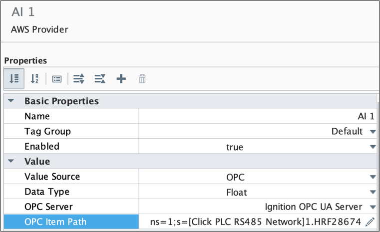
- for an analog input of type Float with a Modbus Holding Register address of 28,674 from Modbus RTU Address 1 would be
- ns=1;s=[Click PLC RS485 Network]1.HRF28674
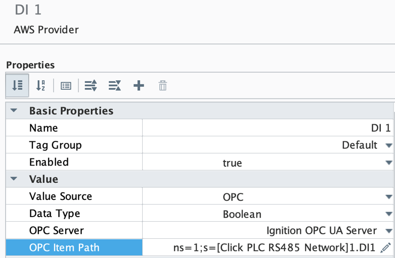
- for a digital input of type Boolean with a Modbus Discrete Input Register address of 1 from Modbus RTU Address 1 would be
- ns=1;s=[Click PLC RS485 Network]1.DI1
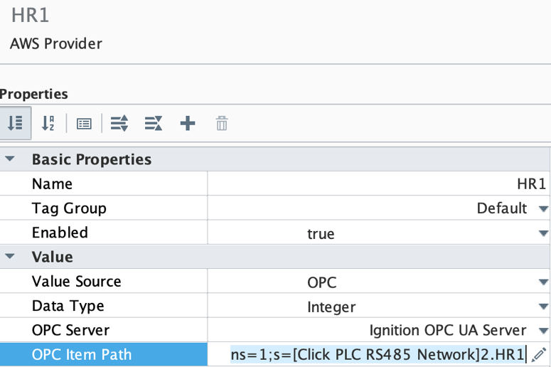
- for an analog input of type Integer with a Modbus Holding Register address of 1 from Modbus RTU Address 3 would be
- ns=1;s=[Click PLC RS485 Network]3.HR1