![]()
Contents
Cirrus Link Resources
Cirrus Link Website![]()
Contact Us (Sales/Support)![]()
Forum![]()
Cirrus Link Modules Docs for Ignition 7.9.x![]()
Inductive Resources
Ignition User Manual![]()
Knowledge Base Articles![]()
Inductive University![]()
Forum![]()
![]()
Cirrus Link Website![]()
Contact Us (Sales/Support)![]()
Forum![]()
Cirrus Link Modules Docs for Ignition 7.9.x![]()
Ignition User Manual![]()
Knowledge Base Articles![]()
Inductive University![]()
Forum![]()
| Anchor | ||||
|---|---|---|---|---|
|
There are four main types of data that the EFM ABB Totalflow driver is capable of getting from an ABB Totalflow device. These are:
...
AARs are polled at a specified interval based on a poll rate and then made available via the OPC-UA interface.
Alarms, events, and history are made available to MQTT Transmission to be published as immutable Record objects to an MQTT server. Typically these would be received by the MQTT Engine and MQTT Recorder modules running on a central Ignition Gateway and inserted into a database for later use or to be made available to other third party systems.
For the purposes of this document there are some definitions that are explained below.
EFM ABB TOTALFLOW → Settings
...
Common File Exchange (CFX) can also be used for these record data.
The quickstart will guide you through setting up
...
the EFM ABB Totalflow
...
driver module and configuring the device connection to:
It will also describe how to use the default Array-Register templates to generate custom templates and poll groups and how to view Alarm, Event, and Periodic and Daily History data
| Anchor | ||||
|---|---|---|---|---|
|
| Anchor | ||||
|---|---|---|---|---|
|
| Module | Parameter | Definition |
|---|---|---|
| EFM ABB Totalflow Settings | Array-Register Definitions (Global) | The global Array-Register definitions made available to the EFM ABB Totalflow module. They are uploaded to the Ignition instance either as individual INI files or as ZIP archives that contain INI files. Note that INI files are text files that are read by PCCU or WinCCU to determine how to display data within an application. These global Array-Register definitions can be referenced by the configurations of the individual ABB Totalflow devices that they apply to. A single Ignition Gateway may contain multiple global Array-Register definitions files that are used to configure Array-Register Templates (i.e. templates that contain array, register, access type, data type, and register name info) for available application types (enumerations) |
| EFM ABB Totalflow Settings | Totalflow Applications Definitions (Global) | The global Totalflow Applications Definitions are uploaded to the Ignition instance as individual CSV files and contain the following information about Totalflow applications:
|
| EFM ABB Totalflow Settings | The periodic mapping files are used for building up EFM Periodic and Daily History records. They map various record fields to database column names so that user can adjust those column names to match requirements. Periodic mappings also allow to exclude certain record fields to be used. They are uploaded to the Ignition instance in the form of specifically formatted CSV files | |
| OPC UA Device Connection | This is a list of applications (fields include respective name, slot number, enumeration, revision and type) that are currently installed on a Totalflow device. This list is obtained either by 'auto-discovery' process that takes place on configuration/restart or by importing specifically formatted CSV file | |
| OPC UA Device Connection | Totalflow Applications Definitions (Device) | These are a subset of the global Totalflow Applications Definition files that apply to a specific device |
| OPC UA Device Connection | These are a subset of the global Array-Register definition files that apply to a specific device | |
| OPC UA Device Connection | Array-Register Templates | Array-Register templates are logical groupings of AARs. Generally, Array-Register templates would be created so that instances of them can be used by specifying a poll group with application slot number |
| OPC UA Device Connection | Poll Groups | Poll groups use Array-Register templates in conjunction with application slot number to create a specific groups of register sets (i.e. sets of consecutive array registers) to be polled at a specified poll rate |
| Tip |
|---|
The Cirrus Link default Array-Register Definitions and EFM Periodic Mapping files can be used as a starting point for configuring the EFM ABB Totalflow module. The Totalflow Application Definitions file can be used as an example if you need to add application definitions that are not known to the driver. |
| Anchor | ||||
|---|---|---|---|---|
|
There are 12 basic steps to getting all of the data available from an ABB Totalflow into Ignition
From the EFM ABB Totalflow Settings, define/upload the global Array-Register definitions available for all Totalflow devices in this Ignition instance
From the EFM ABB Totalflow Settings, define/upload the global Totalflow applications definitions available for all Totalflow devices in this Ignition instance.
| Note |
|---|
| This step is optional since many application definitions are provided by the driver by default. |
Navigate to the 'Array-Register Templates' configuration panel. If 'Auto-Generate Templates and Poll Group' is enabled, verify the default templates are added to this device definition. If this configuration option is disabled, manually import the templates that apply.
| Note |
|---|
| How does the ABB Totalflow driver select which files to parse from the supplied INI file? |
| Warning |
|---|
One default Array-Register template will be created per each application type (i.e. application enumeration) given that polling for at least one instance of this application type is enabled in the 'Totalflow Applications' panel. If there are no enabled applications at the time auto-discovery runs for the first time, no Array-Register templates will be created. If there are enabled applications but there are no Array-Register definitions applied to this device connection, or definitions that are applied have no applicable entries based of application enumeration; in this case, Array-Register templates will be created but those templates will have no entries. If applicable Array-Register definitions are added later, templates will be populated. |
| Anchor | ||||
|---|---|---|---|---|
|
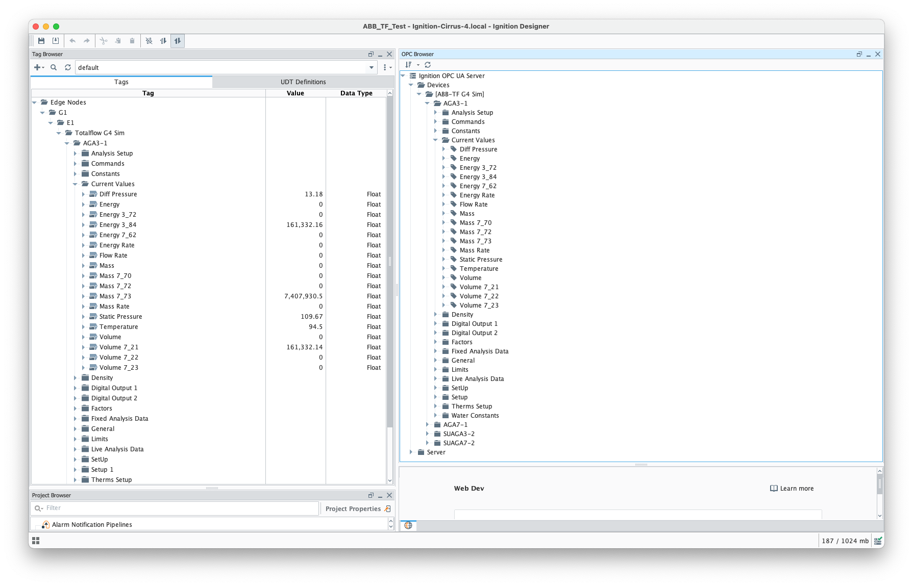
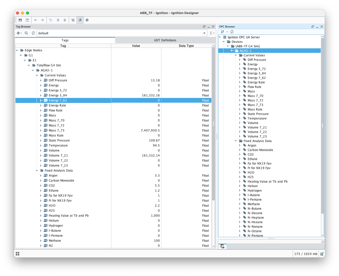
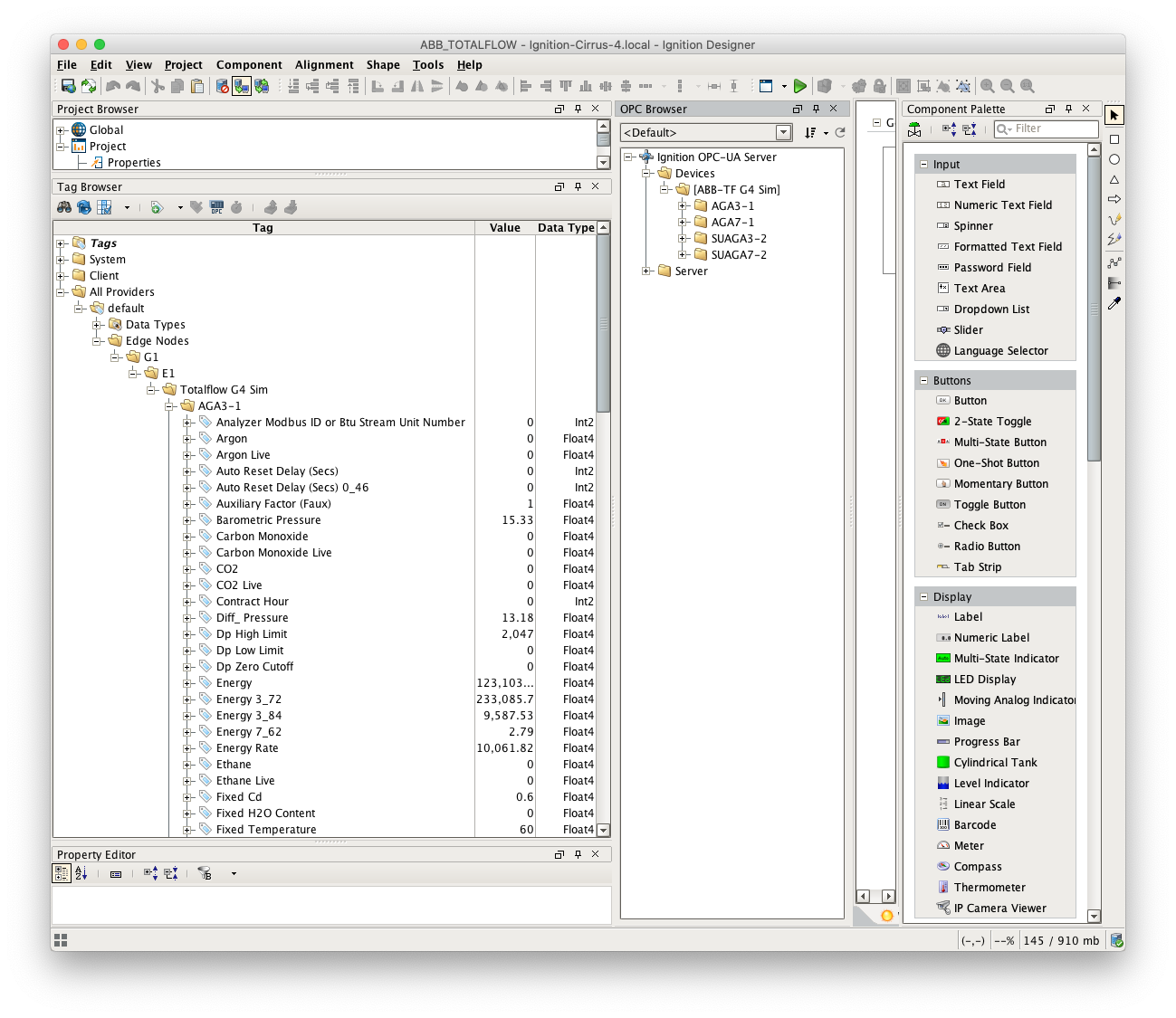
At this point, the ABB Totalflow device should be fully configured. To view data in Ignition launch Ignition Designer and open the OPC Tag Browser as shown below. You should see the tags being polled from the ABB Totalflow device as shown below. You can use these tags as any standard OPC tags in Ignition.
| Anchor | ||||
|---|---|---|---|---|
|
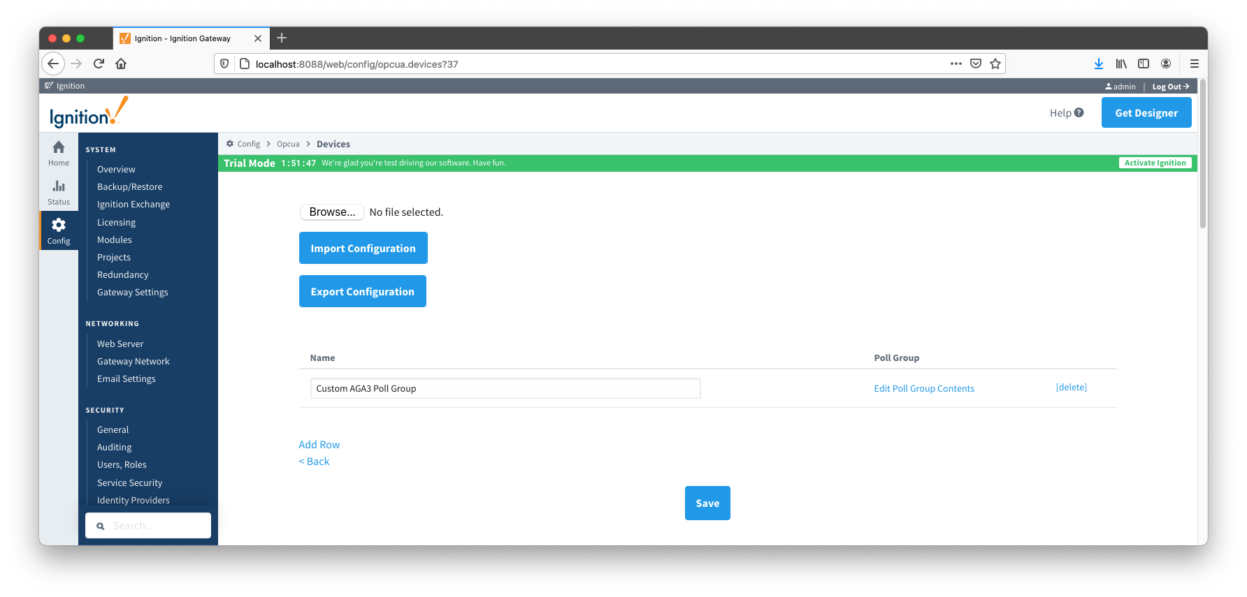
This section will describe how to use default Array-Register templates to generate custom templates and poll groups.
For the purpose of this exercise, lets assume that we only want to poll the AGA3-1 application, and we are interested in 'Current Values' and 'Fixed Analysis' data points only. Here is how to do it:
| Anchor | ||||
|---|---|---|---|---|
|
Record data can be viewed in a couple of ways:
If using Common File Exchange (CFX), the record data will be stored/maintained in CFX.MD5 files on the local Ignition instance. See the ABB Totalflow Device Connection configuration for more details.
These files can be transferred from the Edge device using any method you choose such as FTP but can also be published using the MQTT Transmission File Publishing option.
To do this, you will need to configure an MQTT Transmission File Record and set the CFX File Transfer parameter to point to that File Record and the CFX files can then be automatically published. See the Creating and Publishing Common Exchange File CFX tutorial for details.
To publish and view record data which includes ABB Totalflow alarms, events, and history data you must have MQTT Transmission installed on the instance with the EFM ABB Totalflow driver.
In addition, the following must be set up:
At the Central Gateway:
At the Edge Gateway:
If you do not have a Transmitter configured, create an MQTT Transmitter and set the Sparkplug Settings to the unique Group and Edge Node ID values generated by the Device Connection configuration.
OR
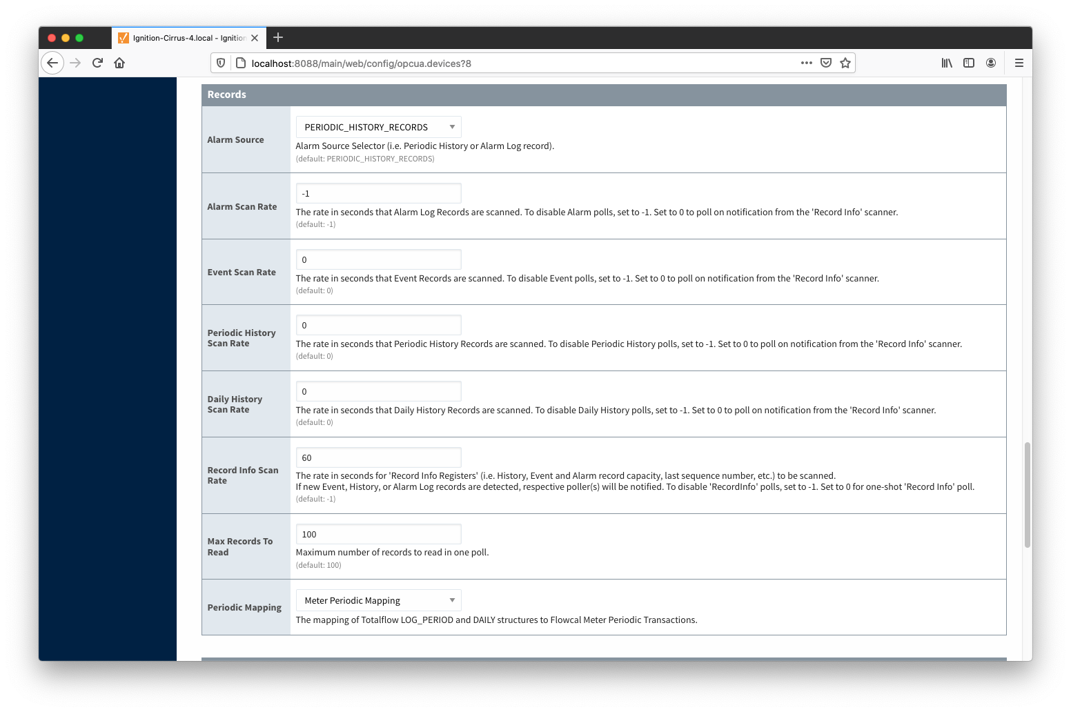
For Events and/or History data set the respective poll rates to zero and set the 'Record Info Scan Rate' option to a positive number
| Note |
|---|
Alarms can come from two sources: PERIODIC_HISTORY_RECORDS - Alarms are obtained from the Log Period records (Array 250) and in this case the 'Alarm Scan Rate' should be set to -1. ALARM_LOG_RECORDS - Alarms are obtained from only meters with the enhanced option turned on |
| Warning |
|---|
| Must have a Sparkplug Group ID and Edge Node ID specified in the Device Connection configuration that matches a Sparkplug Edge Node that MQTT Transmission is reporting on |
When all of these conditions are met, alarm, event, and/or history data will be collected, published, and stored via MQTT Recorder in the configured database.
| Anchor | ||||
|---|---|---|---|---|
|
The Array-Register definition archive file may contain lots of INI files - for example, the Array-Register Definitions zip file above contains 1477 files.
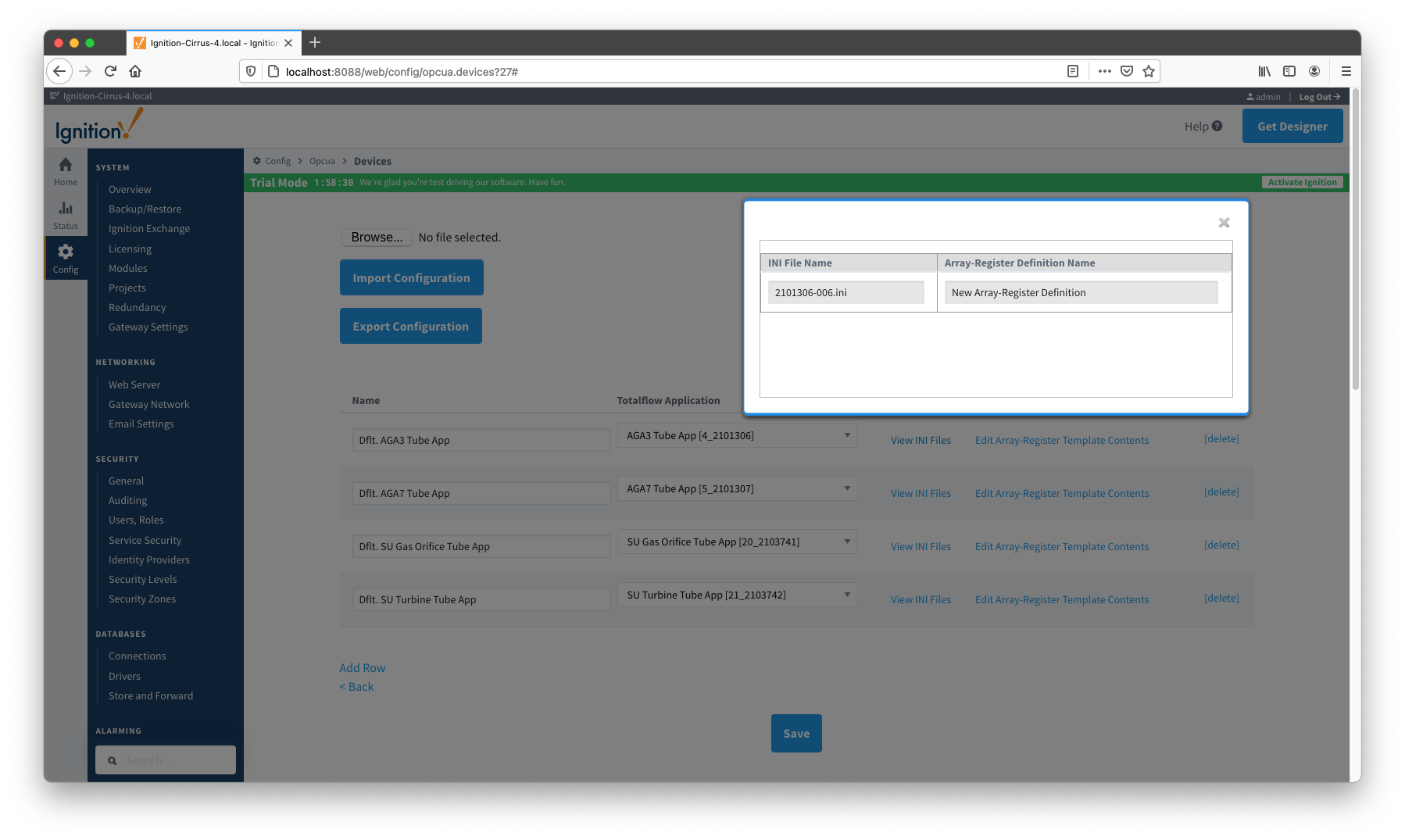
So it worth explaining how the ABB Totalflow driver selects which files to parse to create Array_Regsiter Templates. When global Array-Register definitions are applied to a device connection, the driver uses application revision information obtained during the 'auto-discovery' process and selects INI file names that match application revision and variant numbers. As an example, below is application information obtained during the auto-discovery:
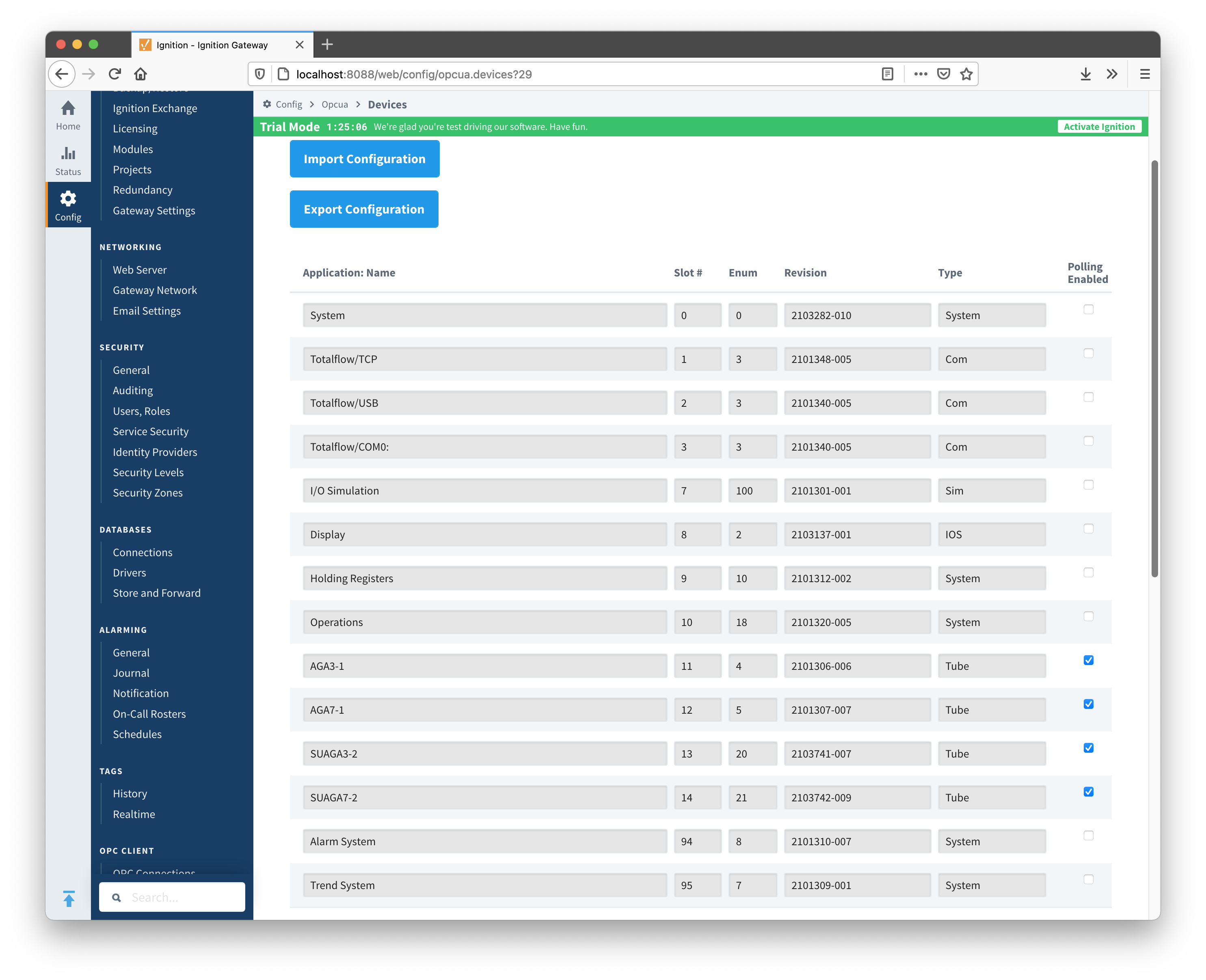
Note that since the revision number for the AGA3-1 meter application is 2101306-006, the INI parser will look for the 2101306-006.ini file in submitted ZIP archive.
If no direct match is found, it will look for the another possible match based on the revision number (i.e. 2101306) and revision variant (i.e. 005 and lower).
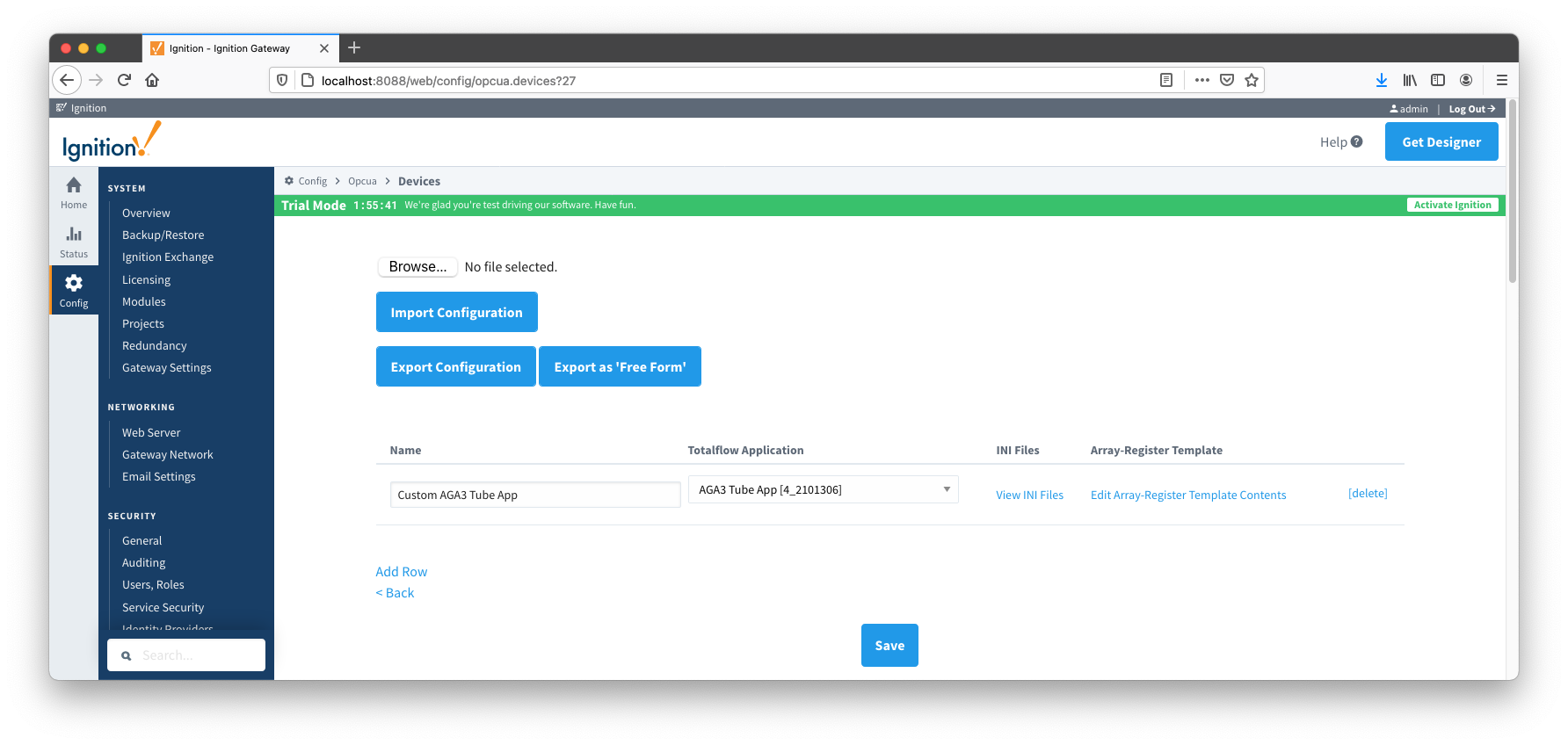
A user can check what INI files were picked by the driver as a source of Array-Register definitions. This information can be obtained form default Array-Register template generated by the driver by following the 'View INI Files' link as shown below: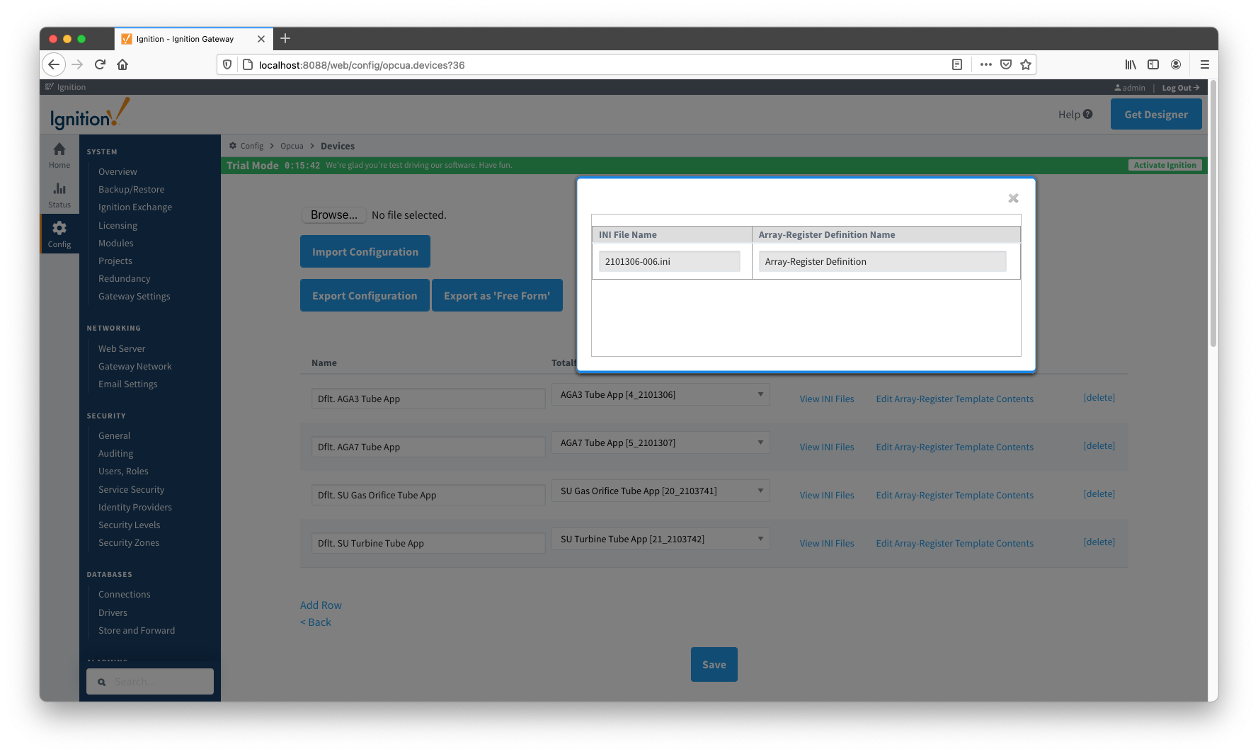
Below is an example that shows a portion the 2101306-006.ini file for the AGA3 Tube Application:
[Live Analysis Data] ExtHlp 5000 Help 1171 #Columns=2,Description=300,Value=100
dsc:Last Update from THERMS;cmd:4.5.1;typ:S;rwa:1;
dsc:Last Update from Other Source;cmd:4.2.2;typ:D;rwa:1;
dsc:Heating Value Live @ Tb and Pb;cmd:4.3.45;typ:F;
dsc:Real Relative Density Live @ Tb and Pb;cmd:4.3.44;typ:F;
dsc:N2 Live;cmd:4.3.46;typ:F;
dsc:CO2 Live;cmd:4.3.47;typ:F;
dsc:Methane Live;cmd:4.3.51;typ:F;
dsc:H2S Live;cmd:4.3.48;typ:F;
dsc:H2O Live;cmd:4.3.49;typ:F;
dsc:Helium Live;cmd:4.3.50;typ:F;
dsc:Ethane Live;cmd:4.3.52;typ:F;
dsc:Propane Live;cmd:4.3.53;typ:F;
dsc:N-Butane Live;cmd:4.3.54;typ:F;
dsc:I-Butane Live;cmd:4.3.55;typ:F;
dsc:N-Pentane Live;cmd:4.3.56;typ:F;
dsc:I-Pentane Live;cmd:4.3.57;typ:F;
dsc:N-Hexane Live;cmd:4.3.58;typ:F;
dsc:N-Heptane Live;cmd:4.3.59;typ:F;
dsc:N-Octane Live;cmd:4.3.60;typ:F;
dsc:N-Nonane Live;cmd:4.3.61;typ:F;
dsc:N-Decane Live;cmd:4.3.62;typ:F;
dsc:Oxygen Live;cmd:4.3.63;typ:F;
dsc:Carbon Monoxide Live;cmd:4.3.64;typ:F;
dsc:Hydrogen Live;cmd:4.3.65;typ:F;
dsc:Argon Live;cmd:4.3.66;typ:F;
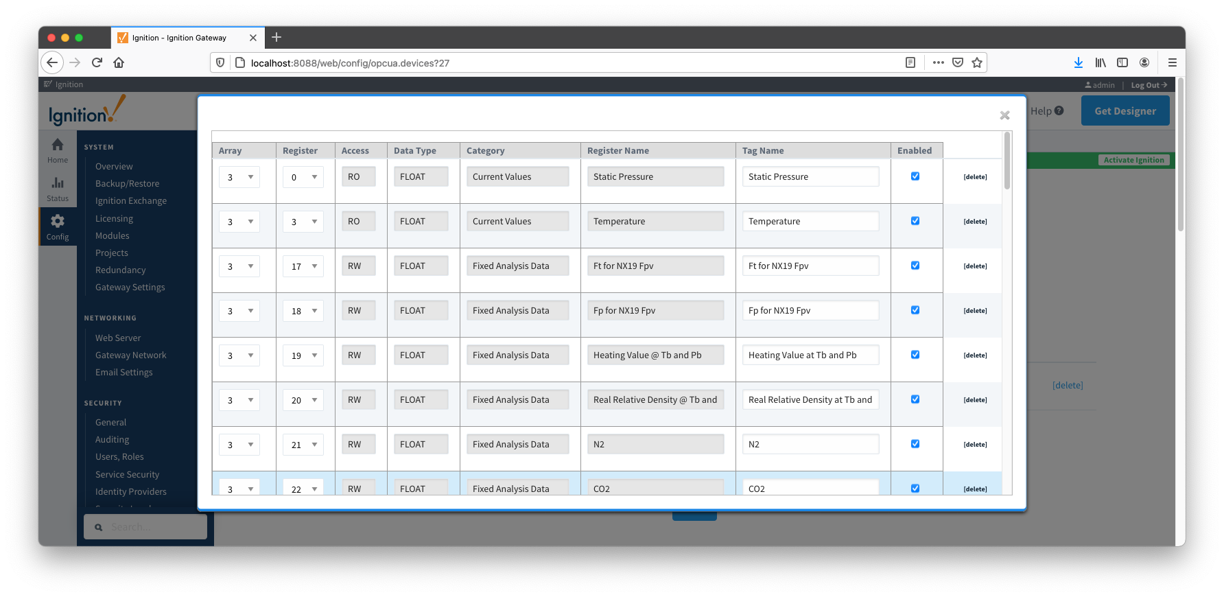
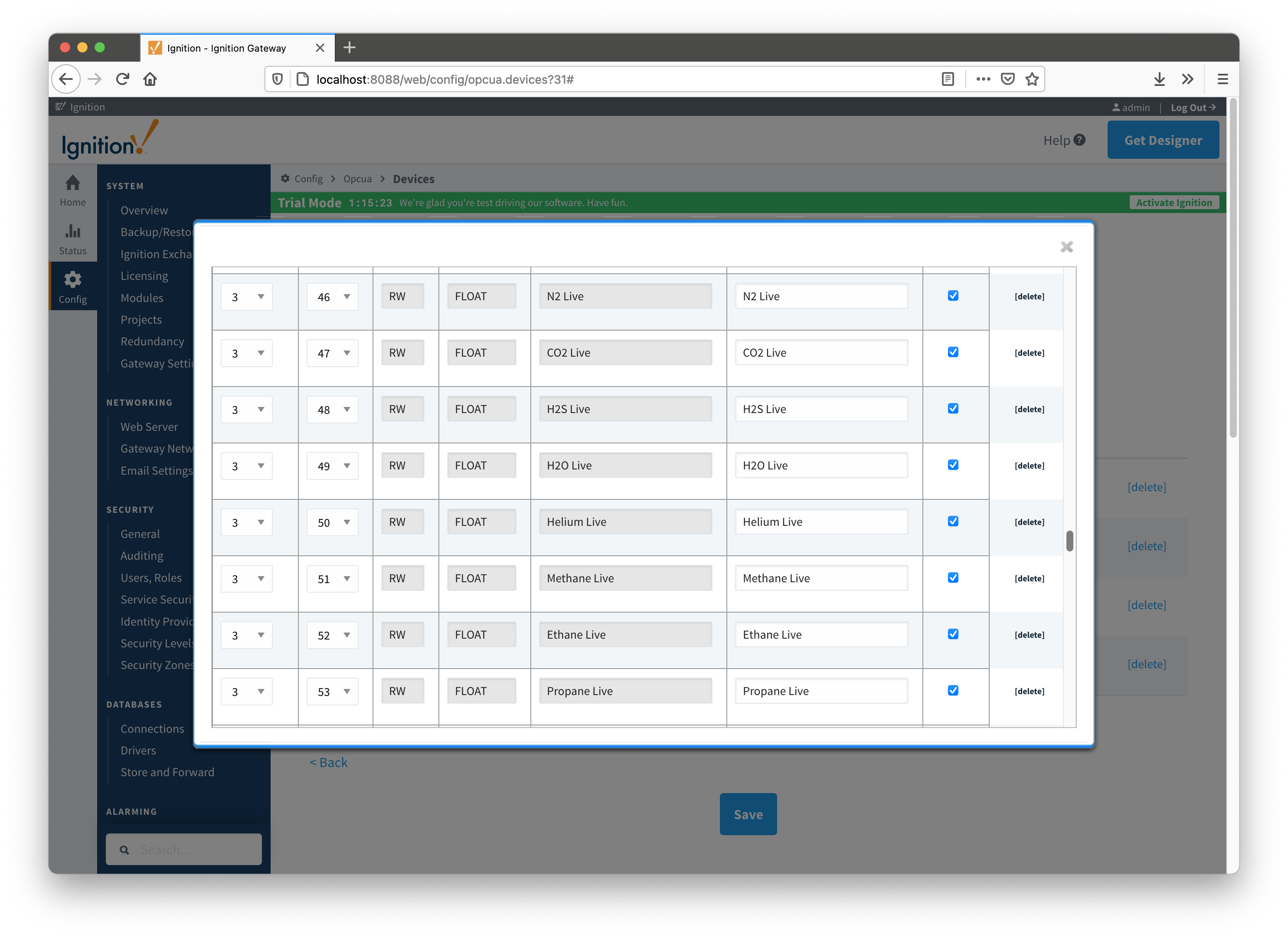
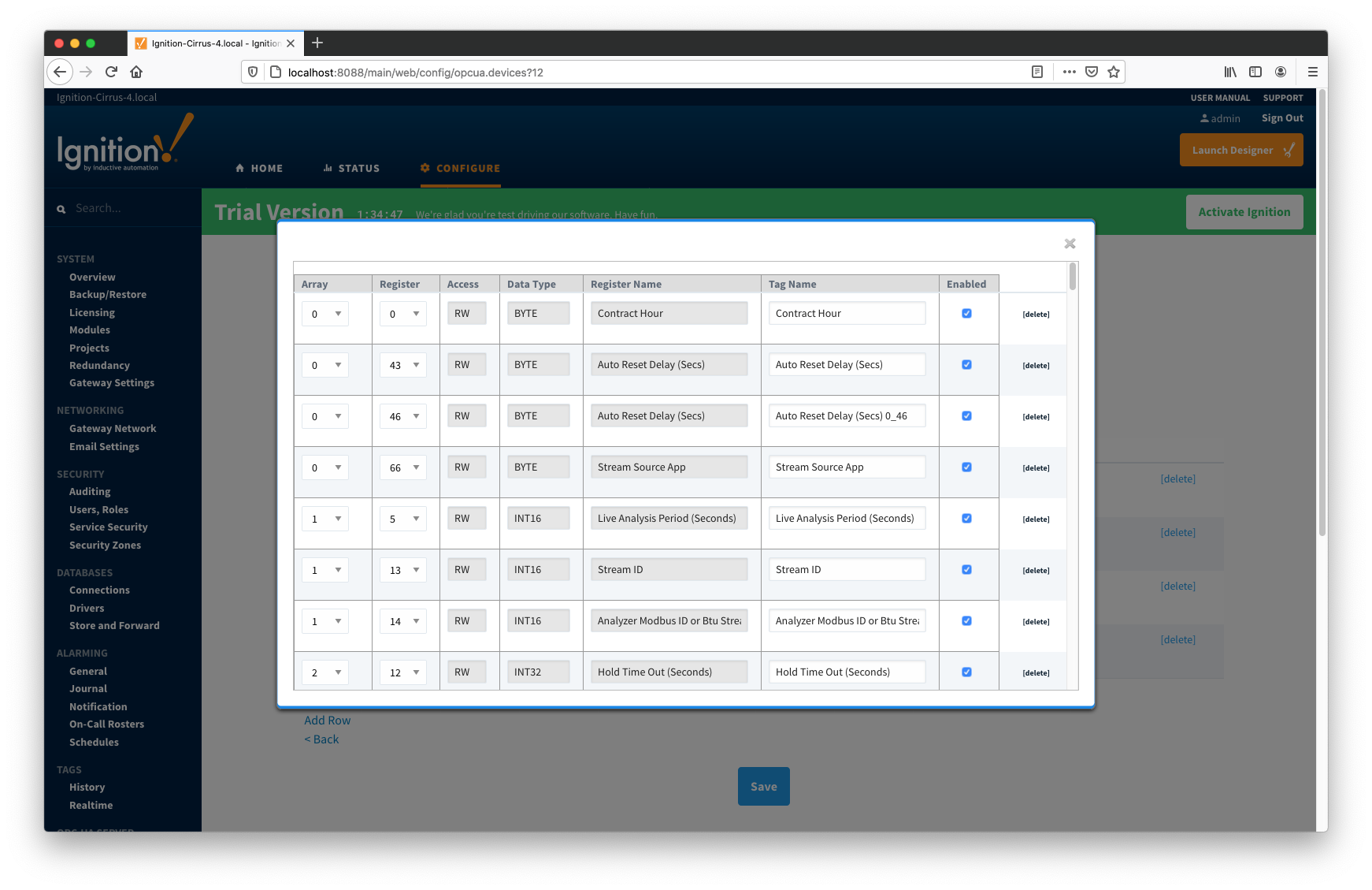
The ABB Totalflow driver parses selected INI file and uses the info (Array-Register definitions) to generate Array-Register templates as shown below.
Note how highlighted (bold) lines shown above correlate to Array-Register Templates shown below.
Let's look at the 'dsc:N2 Live;cmd:4.3.46;typ:F;' line in more detail. The point description (i.e. N2 Live) is being used as a tag name. The 'typ:F' is the data type (i.e. floating point). Finally, the '4.3.46' defines the AAR (i.e. application, array, and register).
| Note |
|---|
| 4 is not an application slot number but application enumeration. |
As a result, a default Array-Register Template is generated by the driver for a specific application enumeration, and it contains all Array-Register points found in appropriate INI files.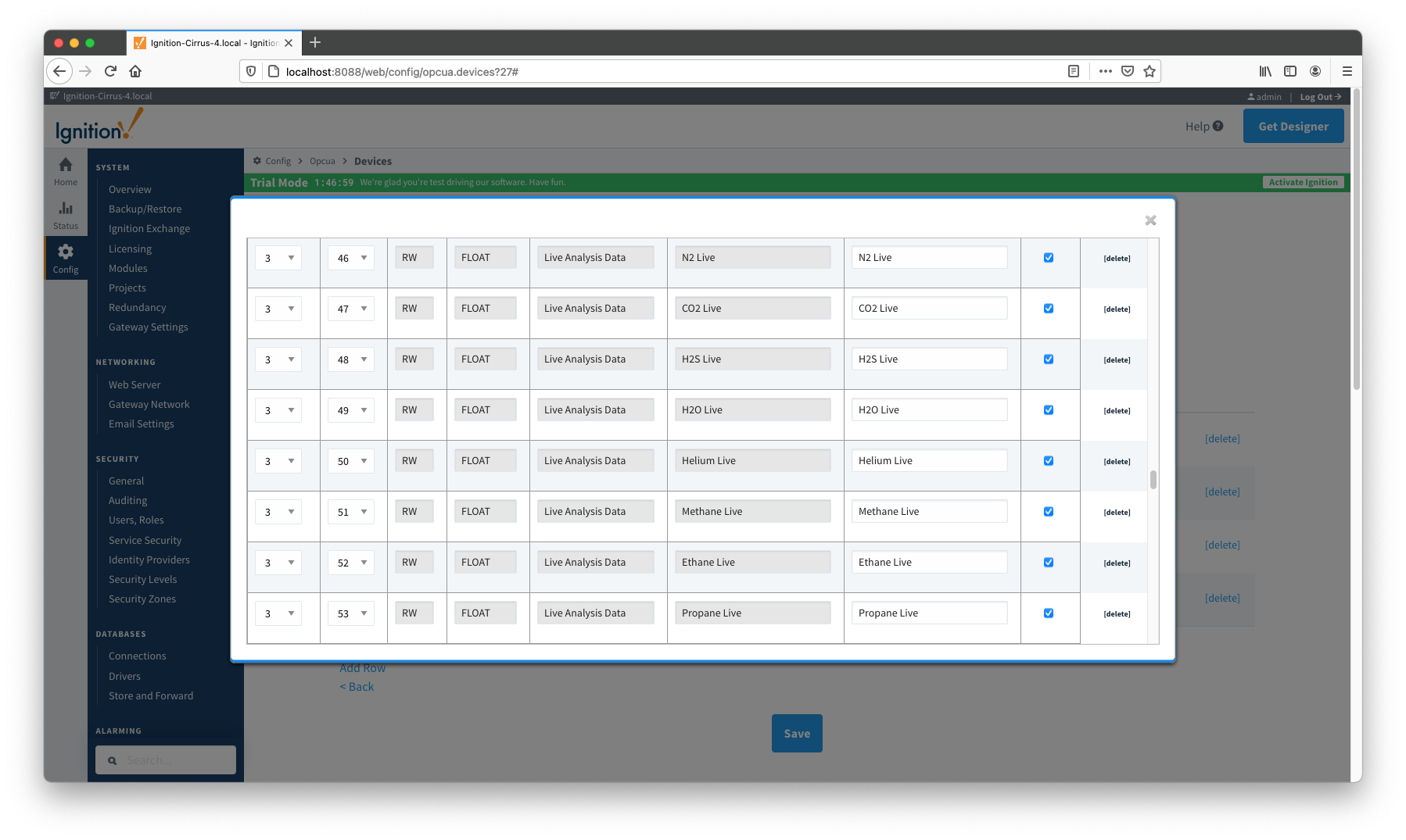
| Excerpt Include | ||||||
|---|---|---|---|---|---|---|
|
OPC-UA SERVER → Devices
There are nine basic steps to getting all of the data available from a ABB Totalflow into Ignition
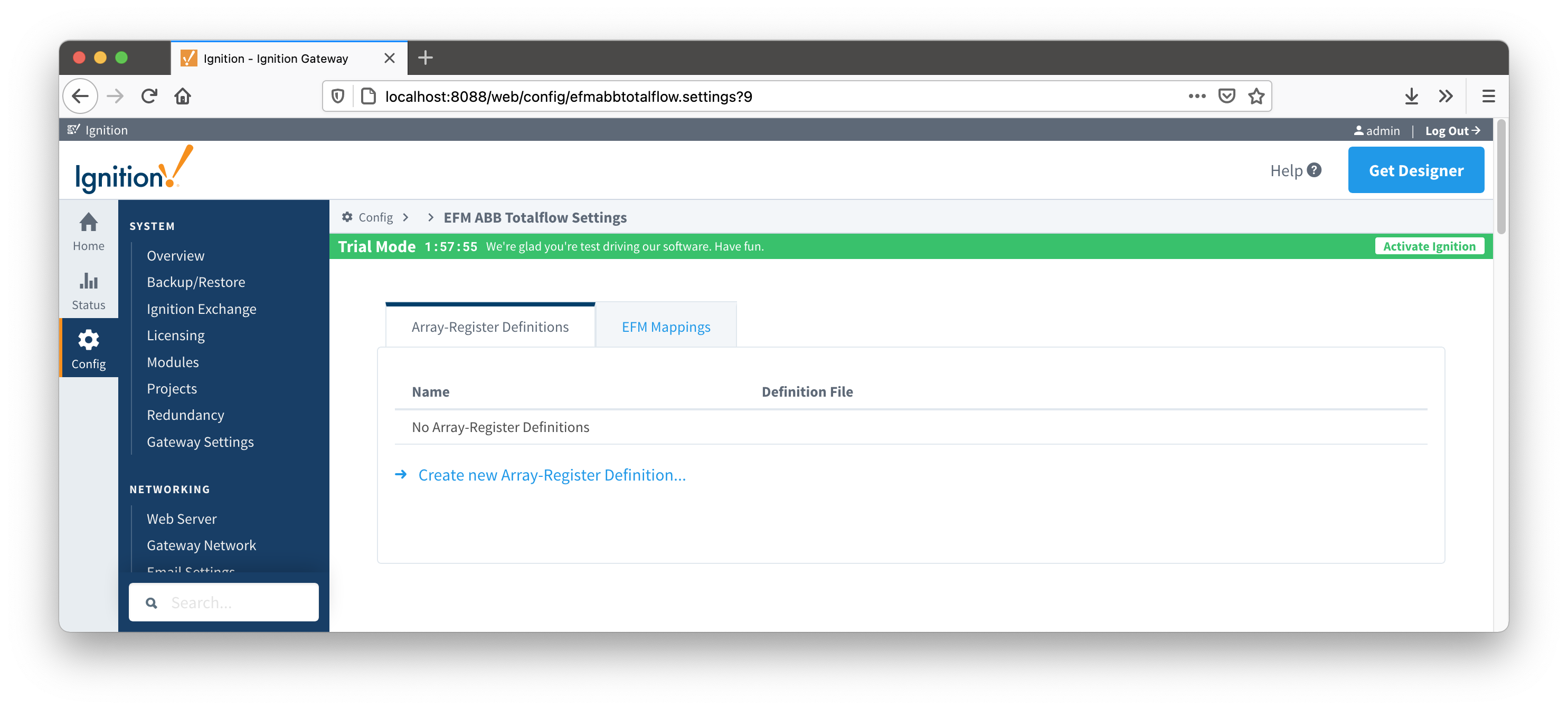
The ABB Totalflow driver module provides a configuration section to the Ignition Gateway. These can be seen in the Configure section of the Ignition Gateway web UI on the left panel near the bottom. Once in the configuration screen there will be a link to create new global Array-Register definitions. Click the link shown below to create a new one.
Note that it is the best practice to add global Array-Register definitions before any Totalflow device connections are defined. If an Array-Register definition is added later, it needs to be added to a device connection manually. Even if device connection has the 'Add All Array-Register Definitions' option turned on, new global Array-Register definition will not be applied unless either added manually or device configuration is re-submitted.
When creating a new global Array-Register definition, only a name and a Totalflow INI file(s) needs to be specified. The name can be any unique name that describes the Array-Register definitions included in submitted file(s). Totalflow INI files are configuration files for use with
PCCU and G2-G5 and NGC devices. Note that multiple Totalflow INI files need to be supplied in a ZIP archive.
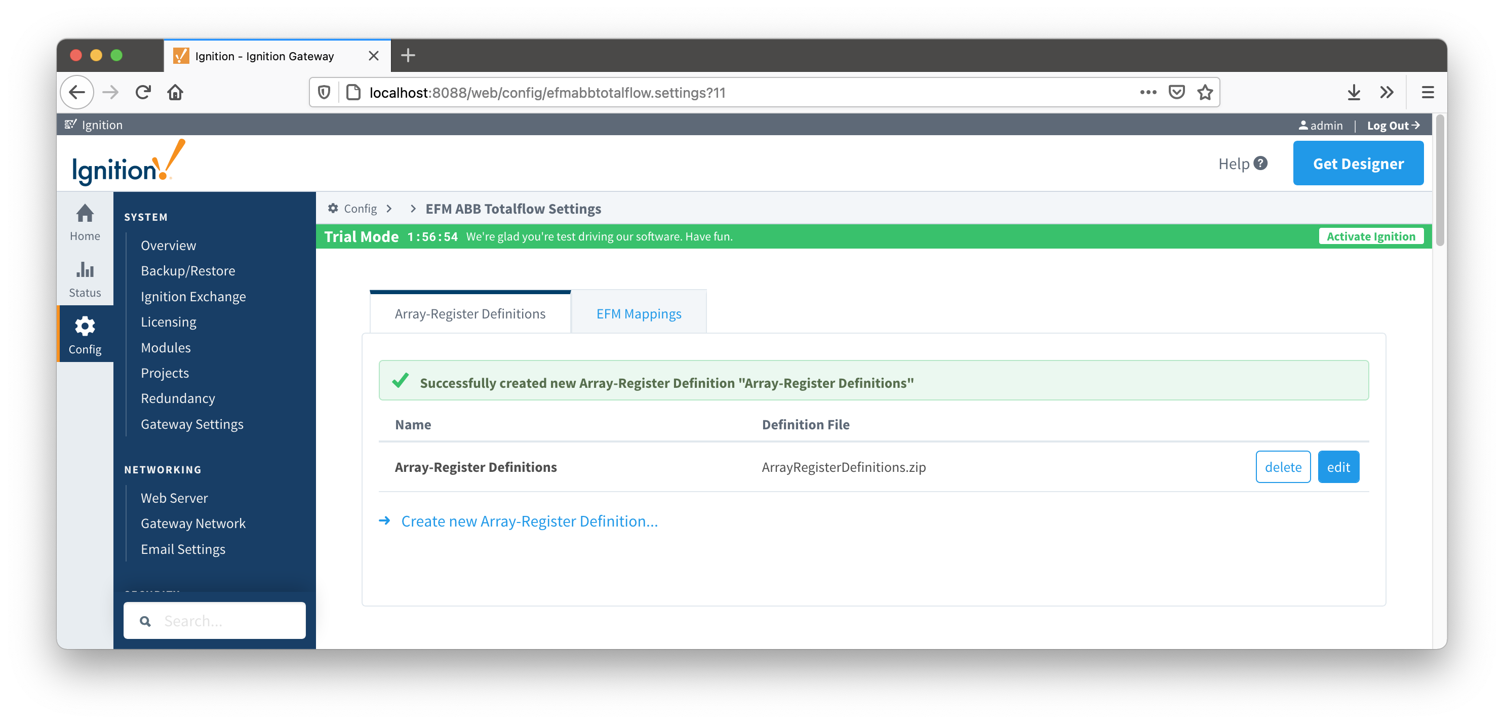
Note that definition archive file may contain lots of INI files. For example, the ArrayRegisterDefinitions.zip file shown above contains 1477 files. So it worth explaining how the ABB Totalflow driver selects which files to parse... When global Array-Register definitions are applied to a device connection, the driver uses application revision information obtained during the 'auto-discovery' process described later in this document and selects INI file names that match application revision and variant numbers. As an example, below is application information obtained during the auto-discovery:
Note that since the revision number for the AGA3-1 meter application is 2101306-006, the INI parser will look for the 2101306-006.ini file in submitted ZIP archive. If no direct match is found, it will look for the another possible match based on the revision number (i.e. 2101306) and revision variant (i.e. 005 and lower). Also note that user has a way to check what INI files were picked by the driver as a source of Array-Register definitions. This information can be obtained form default Array-Register template generated by the driver by following the 'View INI Files' link as shown below:
Below is an example that shows a portion the 2101306-006.ini file for the AGA3 Tube Application:
[Live Analysis Data] ExtHlp 5000 Help 1171 #Columns=2,Description=300,Value=100
dsc:Last Update from THERMS;cmd:4.5.1;typ:S;rwa:1;
dsc:Last Update from Other Source;cmd:4.2.2;typ:D;rwa:1;
dsc:Heating Value Live @ Tb and Pb;cmd:4.3.45;typ:F;
dsc:Real Relative Density Live @ Tb and Pb;cmd:4.3.44;typ:F;
dsc:N2 Live;cmd:4.3.46;typ:F;
dsc:CO2 Live;cmd:4.3.47;typ:F;
dsc:Methane Live;cmd:4.3.51;typ:F;
dsc:H2S Live;cmd:4.3.48;typ:F;
dsc:H2O Live;cmd:4.3.49;typ:F;
dsc:Helium Live;cmd:4.3.50;typ:F;
dsc:Ethane Live;cmd:4.3.52;typ:F;
dsc:Propane Live;cmd:4.3.53;typ:F;
dsc:N-Butane Live;cmd:4.3.54;typ:F;
dsc:I-Butane Live;cmd:4.3.55;typ:F;
dsc:N-Pentane Live;cmd:4.3.56;typ:F;
dsc:I-Pentane Live;cmd:4.3.57;typ:F;
dsc:N-Hexane Live;cmd:4.3.58;typ:F;
dsc:N-Heptane Live;cmd:4.3.59;typ:F;
dsc:N-Octane Live;cmd:4.3.60;typ:F;
dsc:N-Nonane Live;cmd:4.3.61;typ:F;
dsc:N-Decane Live;cmd:4.3.62;typ:F;
dsc:Oxygen Live;cmd:4.3.63;typ:F;
dsc:Carbon Monoxide Live;cmd:4.3.64;typ:F;
dsc:Hydrogen Live;cmd:4.3.65;typ:F;
dsc:Argon Live;cmd:4.3.66;typ:F;
So the driver parses selected INI file and uses the info (i.e. Array-Register definitions) to generate Array-Register templates as shown below. Note how highlighted (bold) lines shown above correlate to Array-Register Templates shown below. Let's look at the 'dsc:N2 Live;cmd:4.3.46;typ:F;' line in more details... The point description (i.e. N2 Live) is being used as a tag name. The 'typ:F' is the data type (i.e. floating point). Finally, the '4.3.46' defines the AAR (i.e. application, array, and register). Note that 4 is not an application slot number, but application enumeration. As a result, a default Array-Register Template is generated by the driver for a specific application enumeration, and it contains all Array-Register points found in appropriate INI files.
The periodic mapping files are used for building up EFM Periodic and Daily History Records. Each row of such file maps specific field of LOG_PERIOD or DAILY records to a database column name. It also allows user to turn a database column off. In other words if column is disabled, respective filed will not be 'recordized'. These mappings are CSV files with the following values:
Below is a mapping example for the LOG_PERIOD_RECORD:
# arrayNum, appEnum, offset, data type, description, column name, enabled
250,4|20,6,FLOAT,Average Differential Pressure,dp_avg,enabled
250,5|21,6,FLOAT,Pulse Counts,pulses,enabled
250,,10,FLOAT,Average Static Pressure,sp_avg,enabled
250,,14,FLOAT,Average Temperature,temp_avg,enabled
250,5|21,18,FLOAT,Uncorrected Volume,raw_vol,enabled
250,,22,FLOAT,Volume,volume,enabled
250,,26,FLOAT,Heating Value,heating_value,enabled
250,,30,UINT16,Flow Time,flo,enabled
250,,32,UINT16,Period Time,flo_rate,enabled
An example of the periodic mapping file can be found here: MeterPeriodicMapping.csv
The Periodic Mappings tab shows all uploaded Periodic Mapping files. This is found via the 'EFM ABB TOTALFLOW' settings on the left 'Config' navigation panel of the Gateway Web UI. It is not part of a specific device connection.
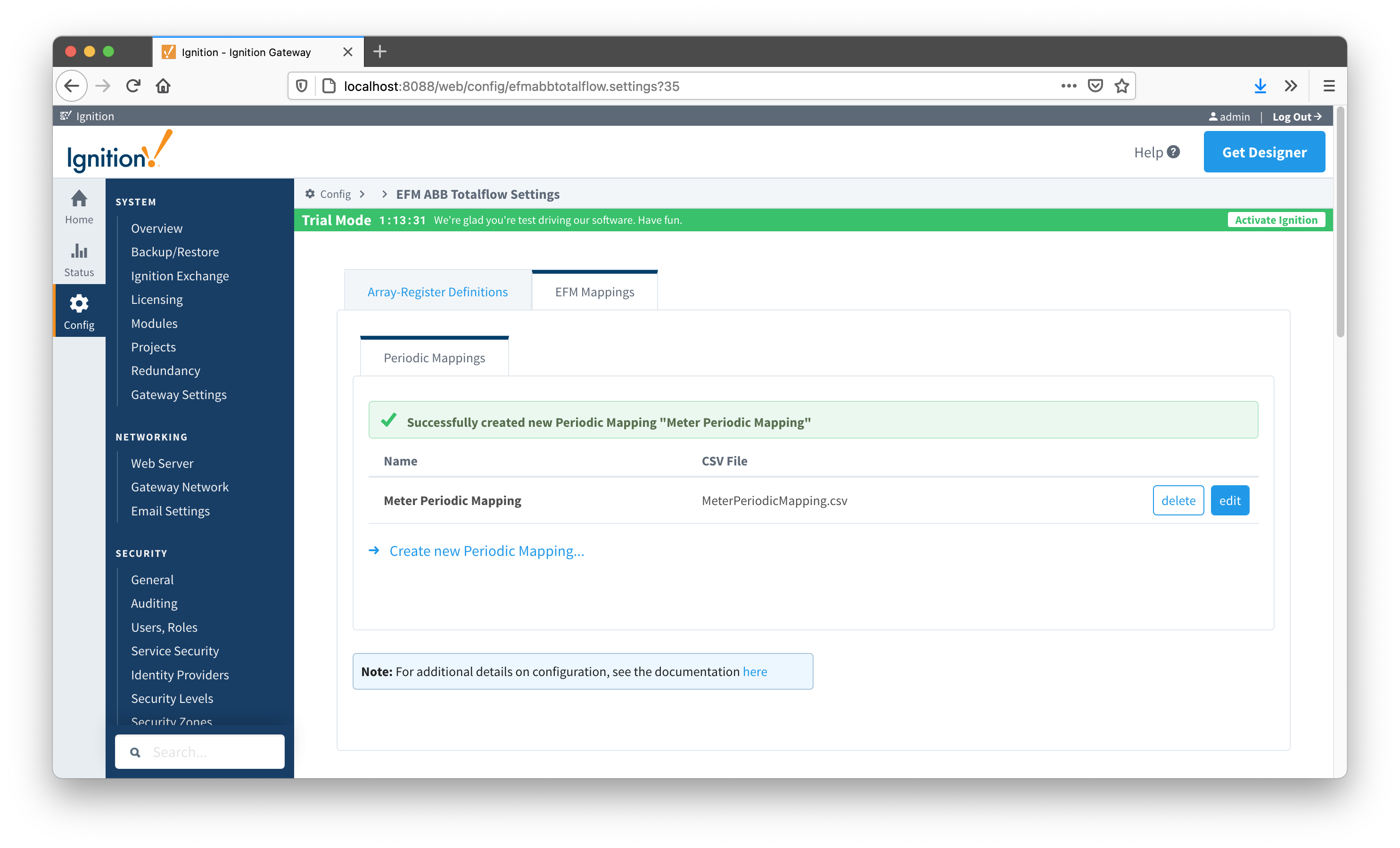
A new Periodic History Mapping can be added by clicking on the "Create New Periodic Mapping..." link.
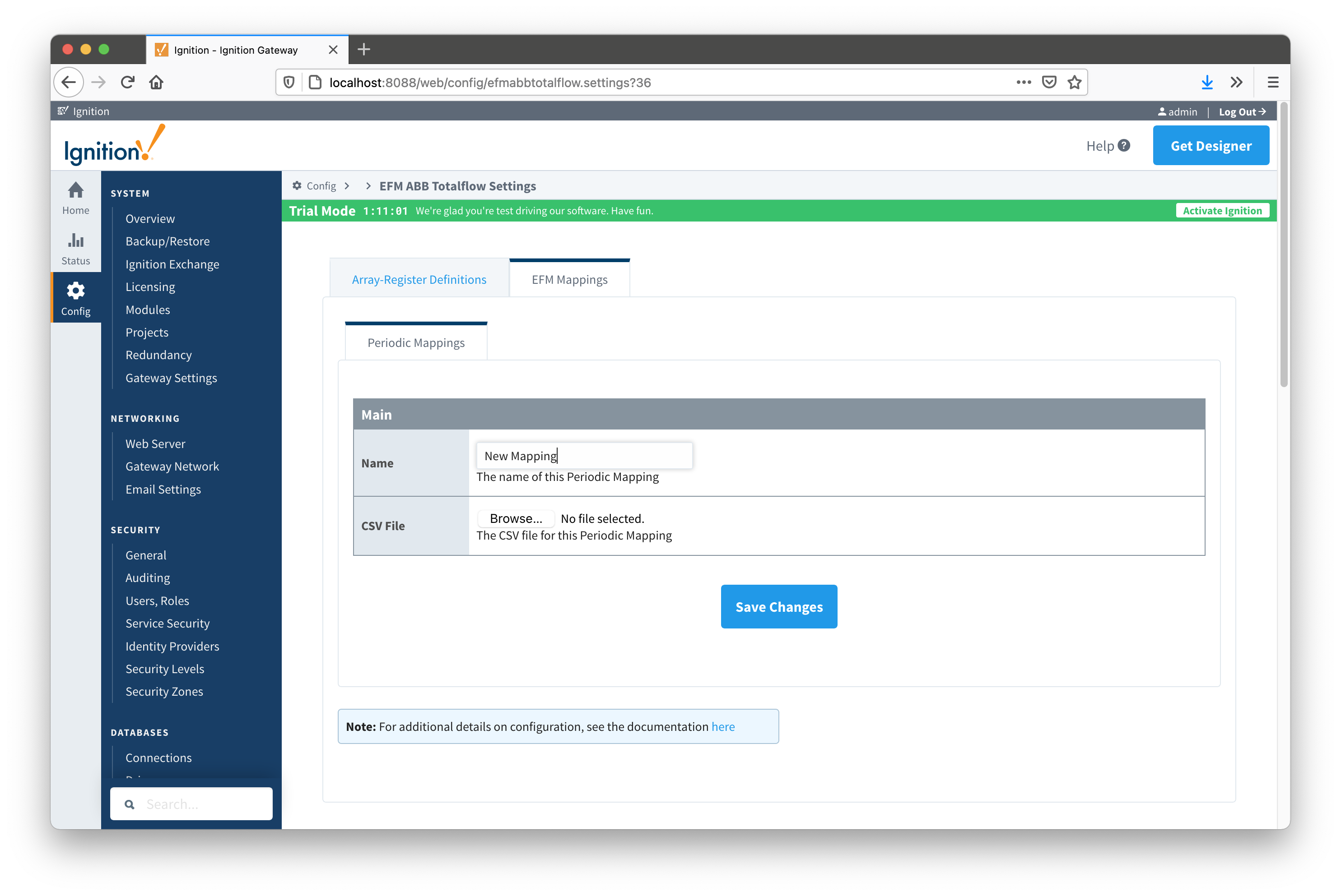
Name
This is the friendly name of the Periodic Mapping being created
CSV File
Click the 'Browse' button to select CSV file for this Periodic Mapping
At this point, device connections can be created using global Array-Register definitions submitted earlier.
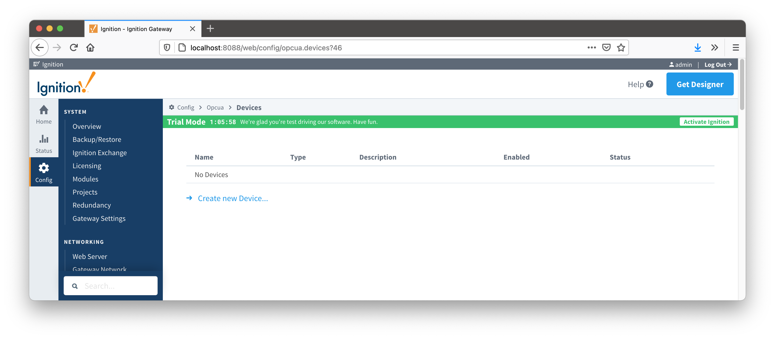
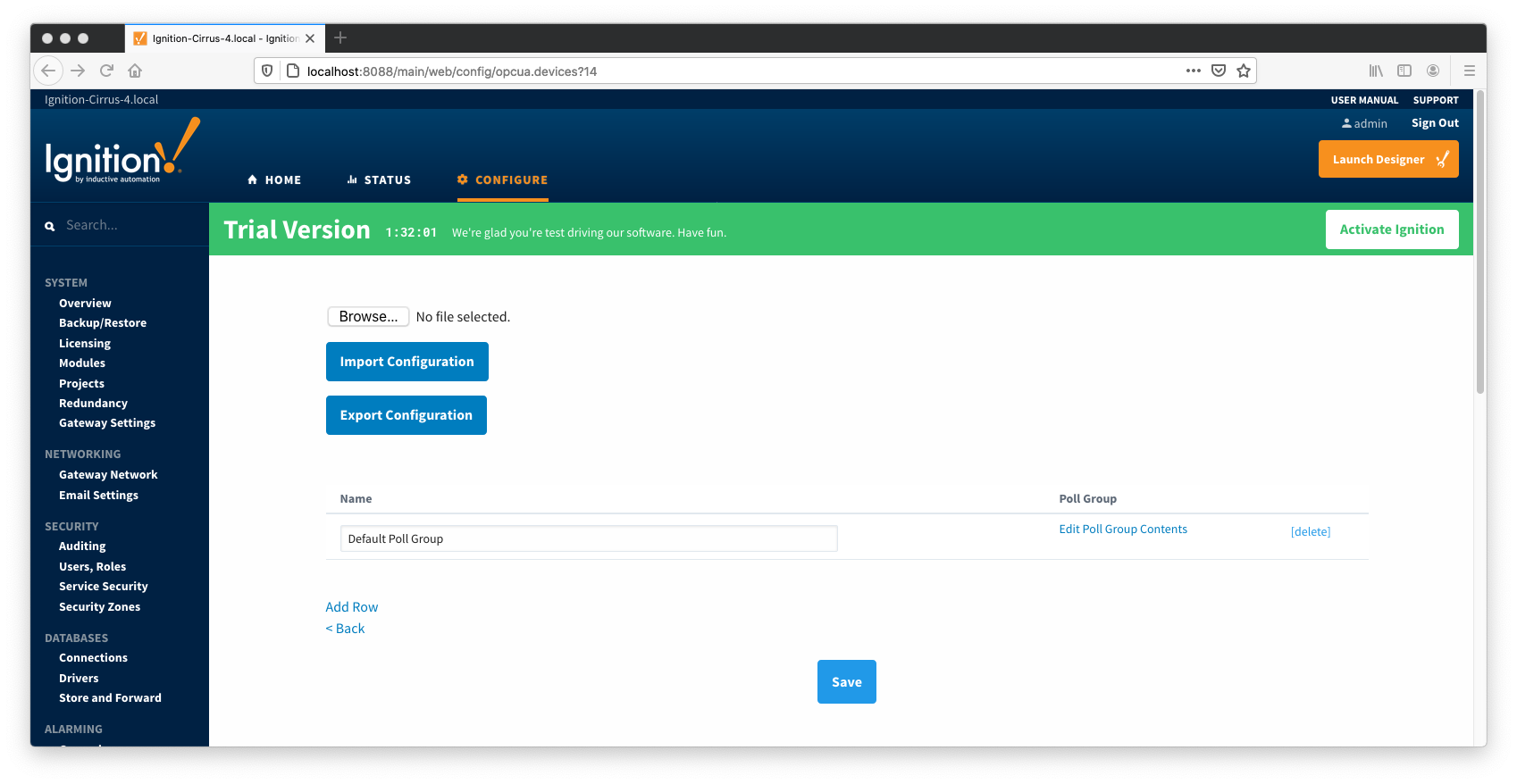
Configuring an ABB Totalflow device connection is done as is with any other driver using the OPC-UA interface. Begin by clicking the Configure tab at the top of the Ignition Gateway web UI and scrolling down to the OPC-UA Server's Devices section and clicking it as shown below.
Once done you will see the following. Click the 'Create new Device...' link to create the ABB Totalflow device connection.
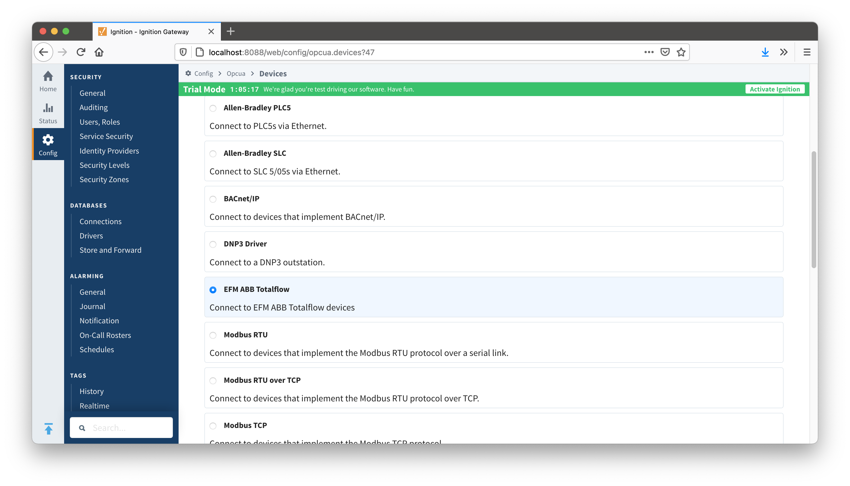
After clicking the 'Create new Device...' link you will see the following. Select the 'EFM ABB Totalflow' and click 'Next' at the bottom of the page.
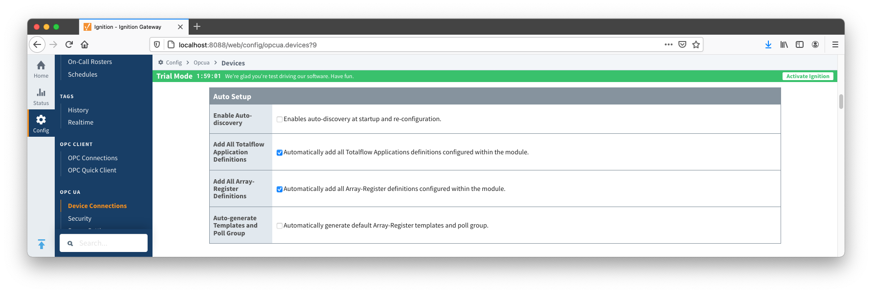
When creating a new device you will see the following:
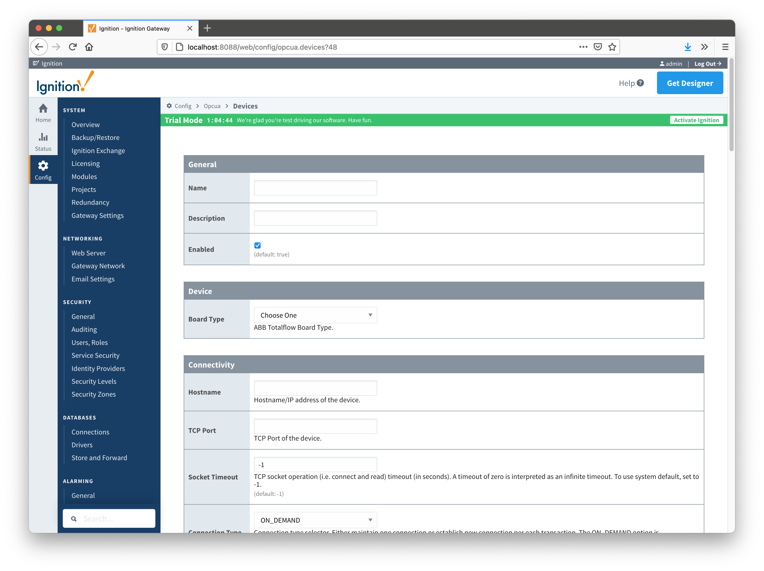
The following describes the parameters that can be set here:
Alarm source selector.
Enables a digital signature field on all Records.
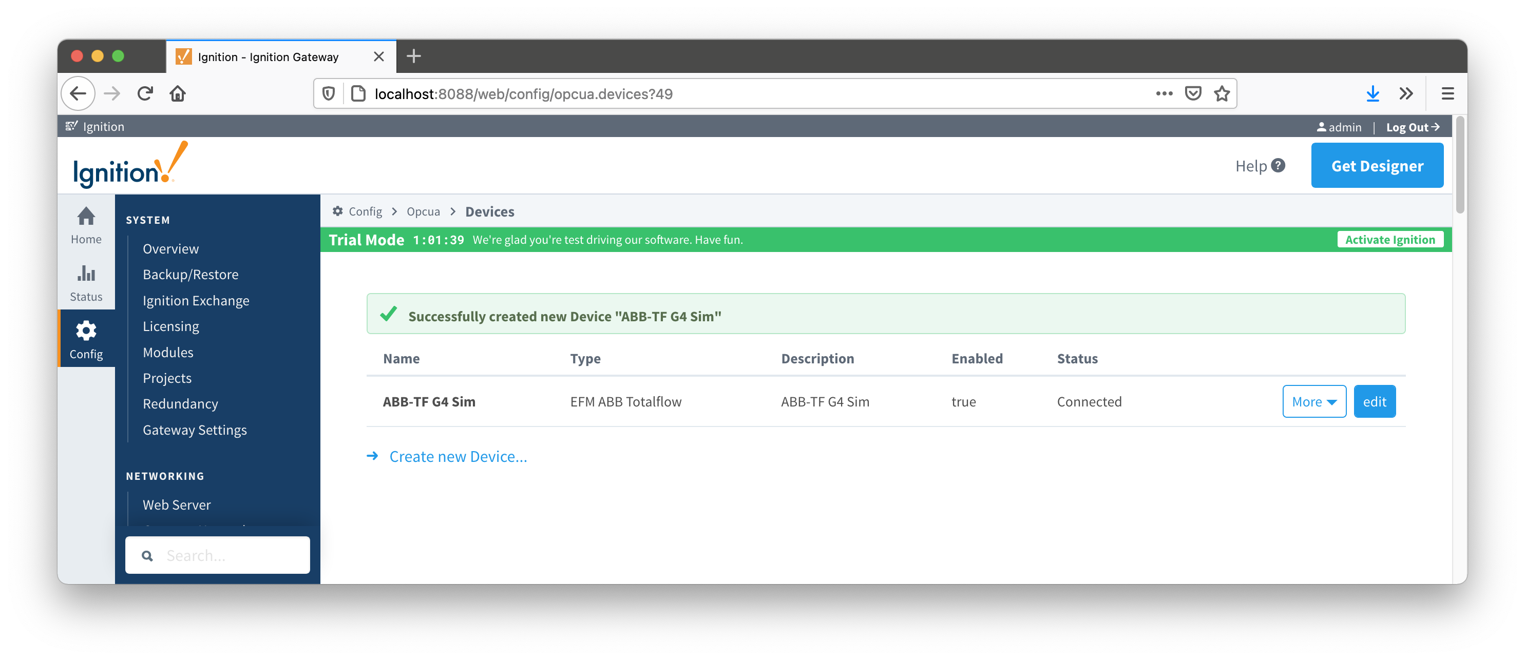
Once the device is created, you should see it is listed in the devices section with a status of either 'Auto-discovery', or 'Connected' on success or "Not Connected" or "Security Failed" on failure.
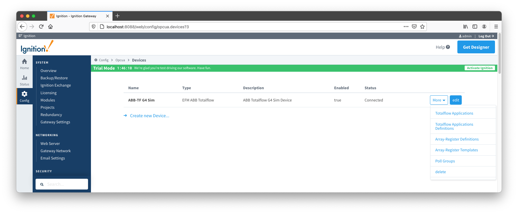
The next sections will show the rest of the configuration that will complete the setup. As a first step, go to the 'Devices' configuration page and click the 'More' button. A drop-down menu with the following five options options will be displayed as shown below:
The 'Totalflow Applications' configuration panel is populated by the 'auto-discovery' process that takes place on device startup or reconfiguration. Below is an example of what can be displayed on this panel:
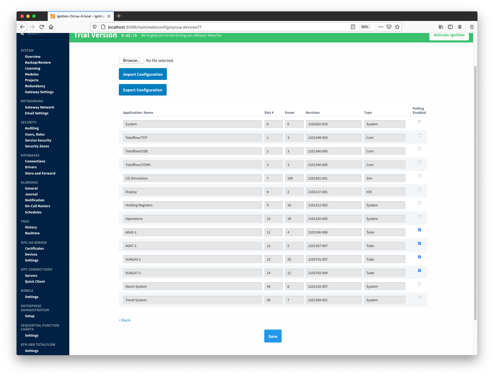
At this point, user can enable or disable polling on any listed application and save the changes. Note that polling on all 'Tube' applications is enabled by default.
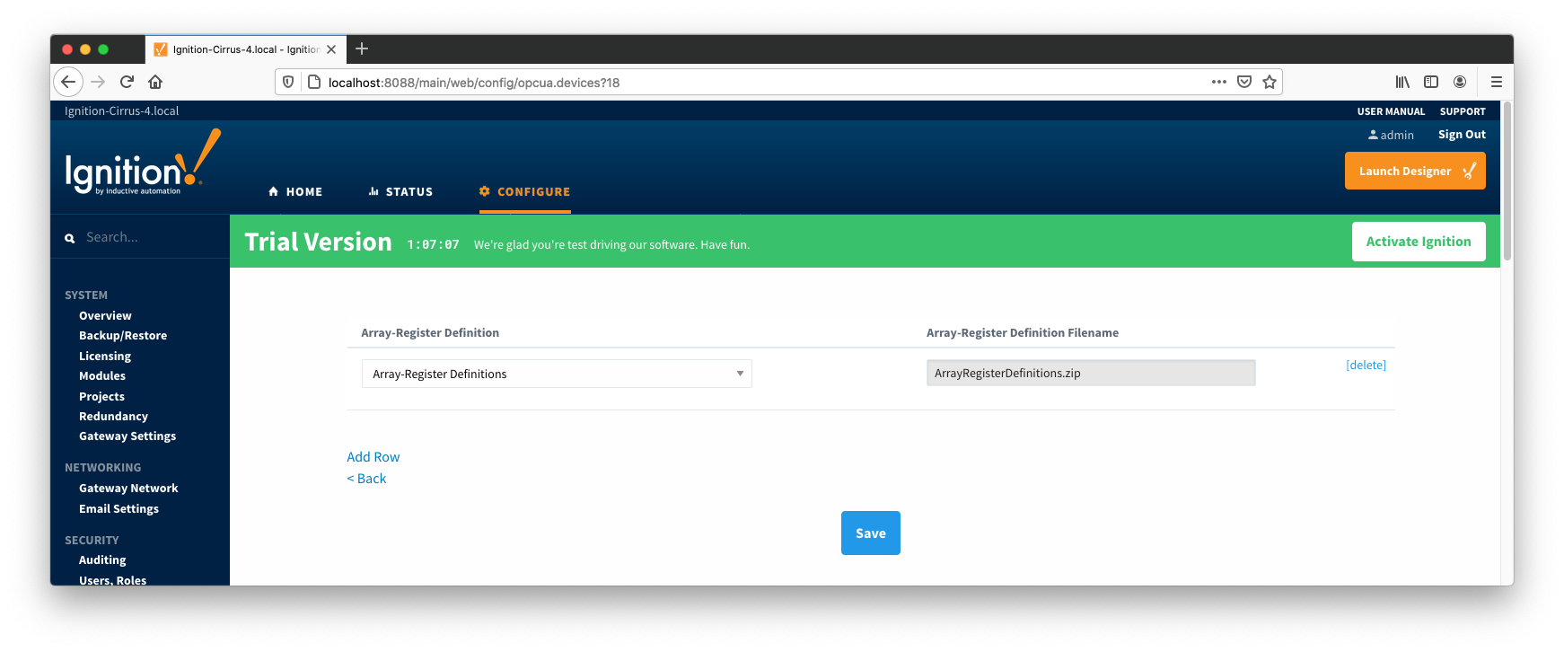
The next step is to add appropriate global Array-Register definitions to this device connection. Do so by clicking the 'More' drop-down button and selecting 'Array-Register Definitions' as shown below:
![]()
You should now see an empty list of Array-Register definitions (unless you used the "Add All Array-Register Definitions" setting). Click the 'Add Row' link that is shown below. This will show a new Array-Register definition with a select box to allow you to select which global Array-Register definition you want to associate with this device. Add as many as are appropriate for your device as shown below:
When complete, save the list and you will be taken back to the Devices list.
With the Array-Register definitions now defined for this device we can create some Array-Register templates to allow creation of Application-Array-Register (AAR) poll groups. Note that the ABB Totalflow driver is capable of generating default Array-Register templates - one per each enabled application type (i.e. application enumeration). If ABB Totalflow device connection was created with the 'Auto-generate Templates and Poll Group' setting turned on, the following default Array-Register templates will be generated for the Totalflow applications shown above:
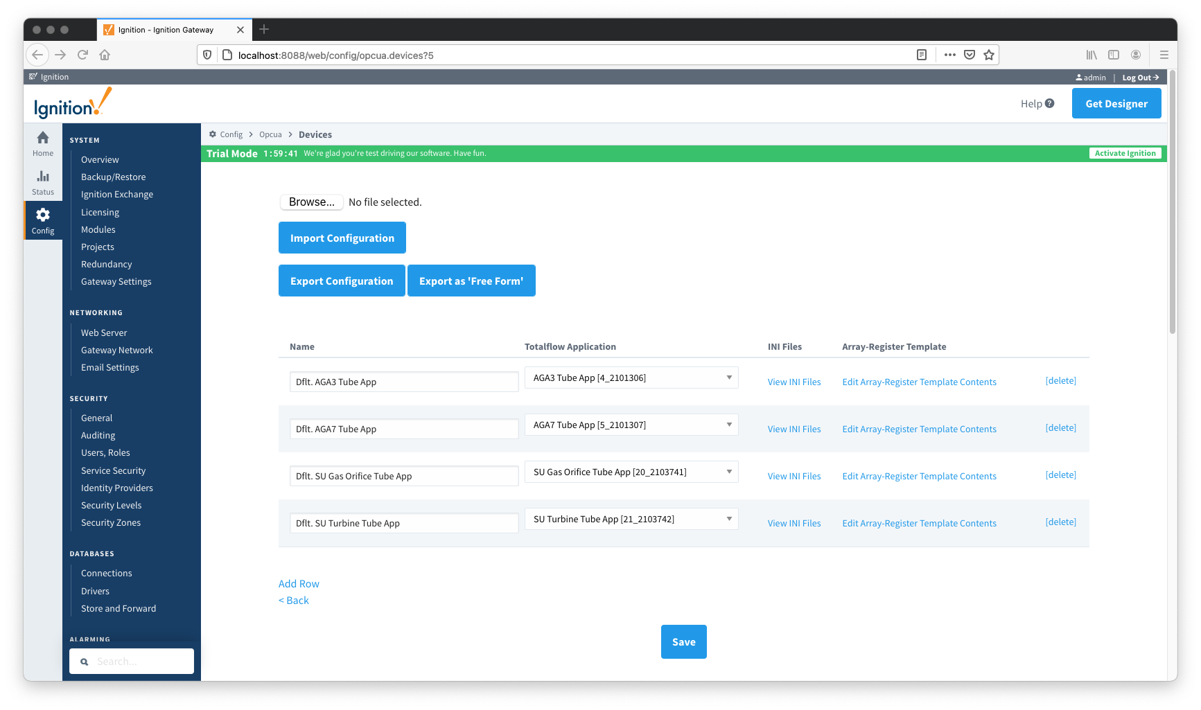
These default templates for each application type will contain all Array-Register points obtained from applied Array-Register definitions that are applicable for this application enumeration. An example of this default template entry page is shown below:
At this point you can do the following:
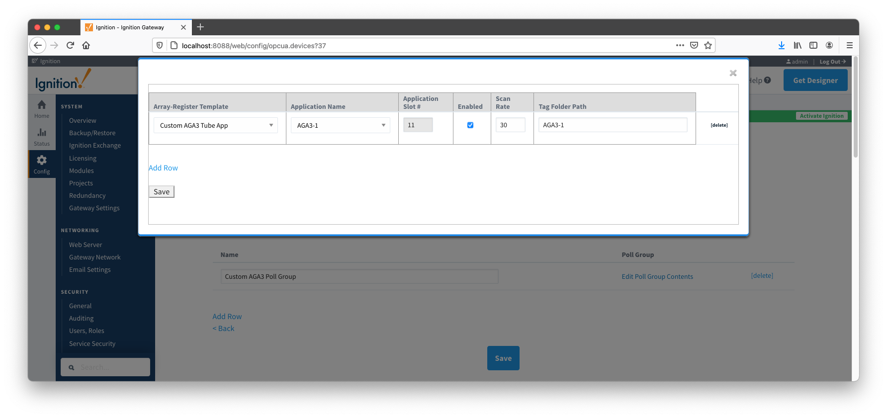
With Array-Register templates already defined, you can now create Application-Array-Register (AAR) poll groups. Note that if ABB Totalflow device connection was created with the 'Auto-generate Templates and Poll Group' setting turned on, the driver will create a default poll group. This default poll group will have one entry per each application enabled on the Totalflow Applications Configuration Panel as shown below:
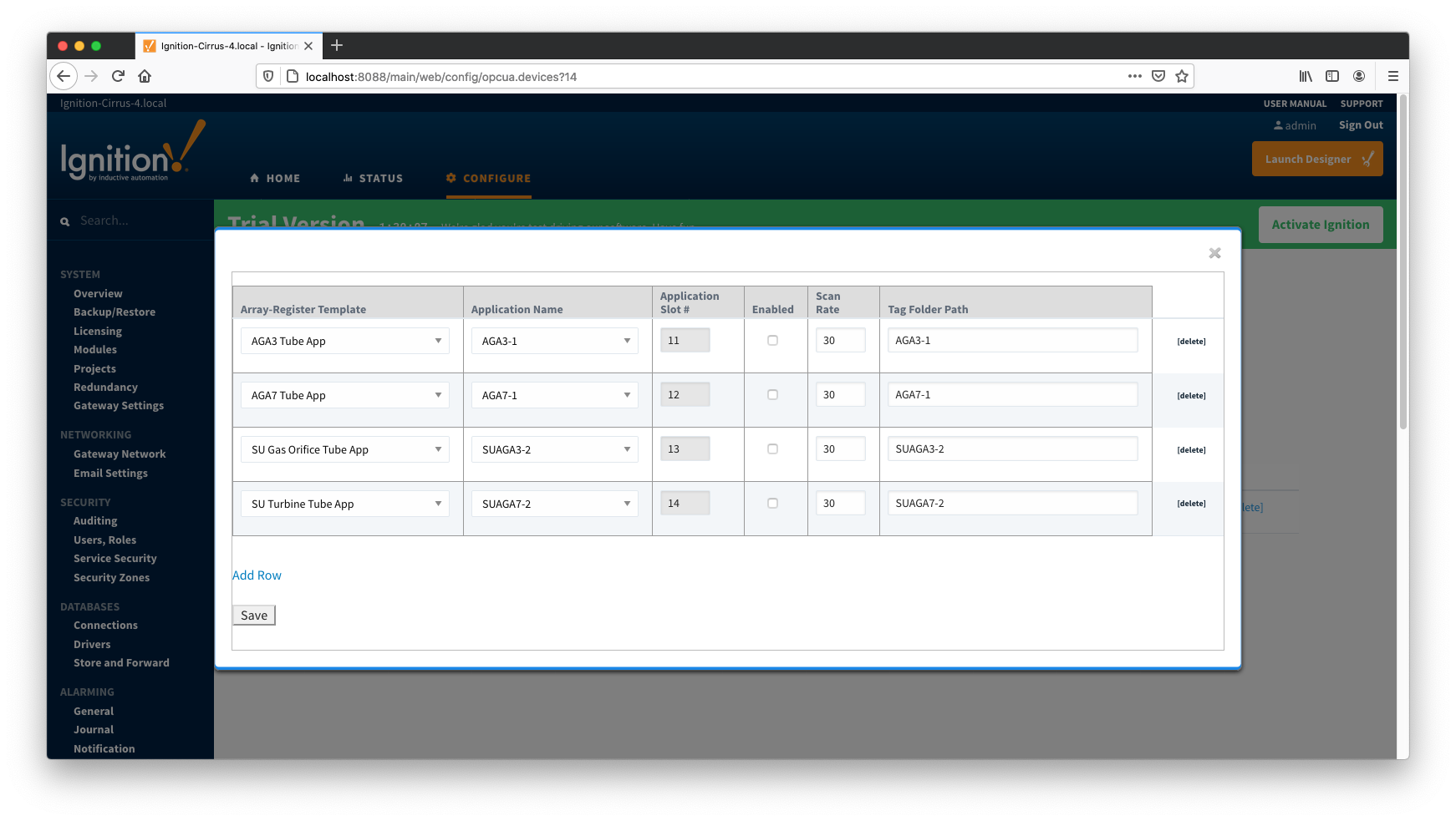
As shown on the picture above, each poll group entry has the following fields:
When a poll group entry is enabled a polling thread is spawned, and this thread polls for data points defined in the Array-Register template this entry points to. And as with Array-Register templates, if a default poll group entry or entire poll group needs to be deleted, it is the best practice to turn the 'Auto-generate Templates and Poll Group' device configuration option off first.
At this point, the ABB Totalflow device should be fully configured. To view data in Ignition launch Ignition Designer and open the OPC Tag Browser as shown below. You should see the tags being polled from the ABB Totalflow device as shown below. You can use these tags as any standard OPC tags in Ignition.
To view record data which includes ABB Totalflow alarms, events, and history data you must have MQTT Transmission installed on the instance with the EFM ABB Totalflow driver. In addition, the following must be set up.

When all of these conditions are met, alarm, event, and/or history data will be collected, published, and stored via MQTT Recorder in the configured database.