![]()
Contents
Cirrus Link Resources
Cirrus Link Website![]()
Contact Us (Sales/Support)![]()
Inductive Resources
Ignition User Manual![]()
Knowledge Base Articles![]()
Inductive University![]()
Forum![]()
![]()
Cirrus Link Website![]()
Contact Us (Sales/Support)![]()
Ignition User Manual![]()
Knowledge Base Articles![]()
Inductive University![]()
Forum![]()
None
The Inductive Auotmation platform and MQTT modules can be resilient to failures when configured to use redundancy. Redundant Ignition systems can be set up and configured to act as failover backups for primary/master Ignition instances. This tutorial will provide step by step instructions for installing a set of Ignition systems with redundancy on the host/primary Ignition instance as well as redundancy on the MQTT enabled edge nodes. For this tutorial we will show how to set up a total of six Ignition systems. These will be:
Additional Edge Nodes could be added to this infrastructure. It is also important to note that the Ignition Edge Nodes with MQTT Transmission could also be instances of Ignition Edge MQTT depending on your requirements (https://inductiveautomation.com/whats-new-ignition-edge). There are additional considerations when setting up a real world system using redundancy. These topics are not covered in this tutorial but should be taken into consideration.
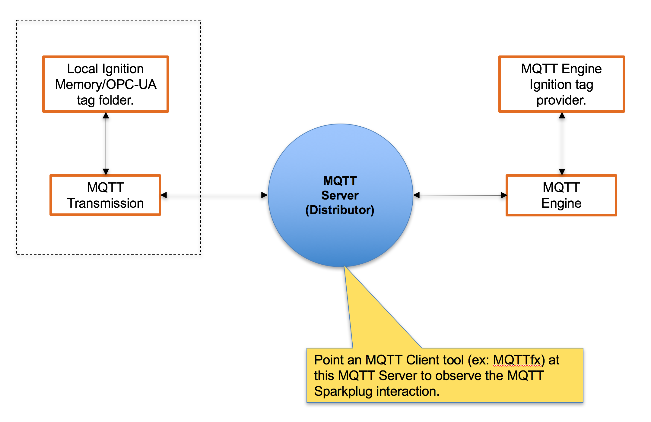
In conjunction with the Sparkplug specification, it is very useful to set up a working system that uses the MQTT Sparkplug specification in order to observe a simple but fully functional system. This section of the tutorial will provide step by step instructions for installing the Ignition Gateway Industrial Application Platform with the following modules:
Upon completion of this tutorial you will have all of the required components to configure, deploy, and observe the Sparkplug MQTT specification in action.
Ignition is an Industrial Application Platform that can be used to create SCADA and HMI solutions. A fully functional Ignition system can be downloaded and run in trial mode. Using Ignition as a tool in this way, we can install the Sparkplug MQTT Modules and observe everything working.
Go to the Inductive Automation download page and download the desired Ignition installer for Windows, Linux or MacOS;
https://inductiveautomation.com/downloads/ignition
Once the Ignition installer has been downloaded, follow the instructions provided by Inductive Automation to install and startup Ignition.
(Note: For this test infrastructure, MQTT Distributor will be installed as an Ignition module. Remember to either turn off firewalls or at a minimum allow inbound connections to TCP/IP port #1883 and port #8883, as remote MQTT Clients will need to be able to establish a TCP/IP socket connection to these ports).
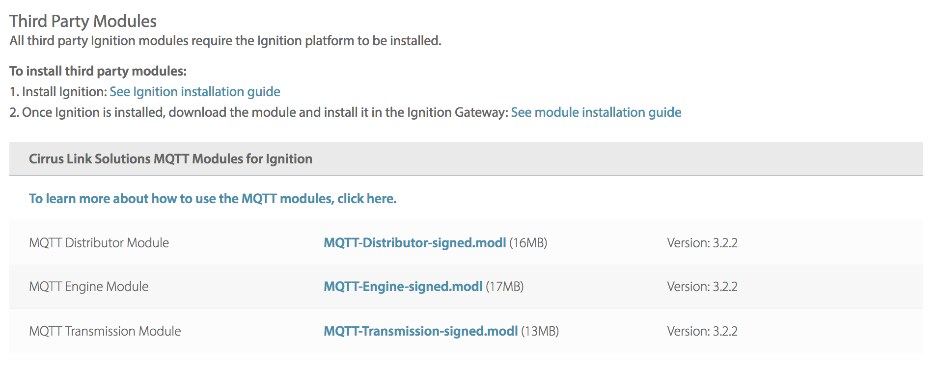
Go to the Inductive Automation download page again and scroll down to the Third Party modules section. Find the Cirrus Link modules section and download the MQTT Distributor, MQTT Engine, MQTT Transmission modules.
https://inductiveautomation.com/downloads/ignition. The download links should look similar to what is shown below.
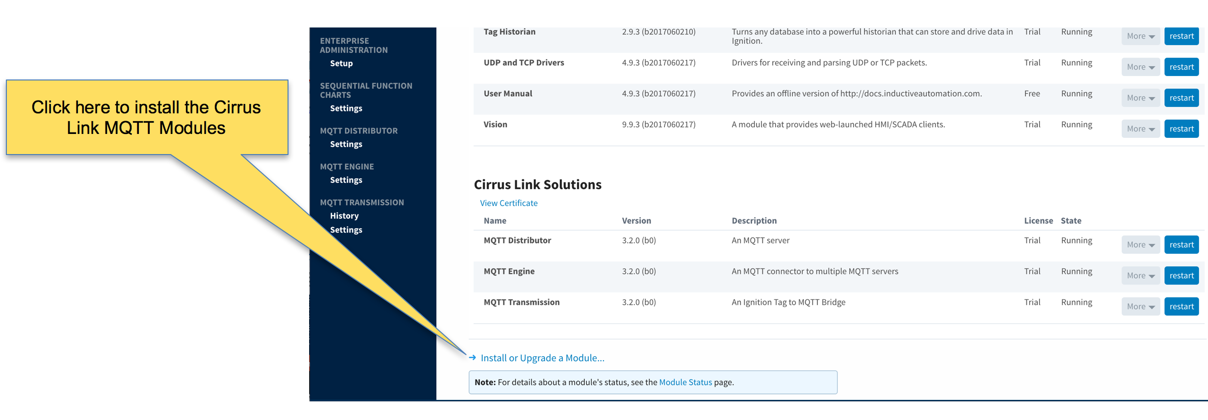
Once you have Ignition installed and running, and the MQTT Distributor, MQTT Engine and MQTT Transmission modules downloaded, browse to the Ignition Gateway console (e.g. http://localhost:8088). Login using the default credentials of admin/password. Click on Configuration tab and then click on the Modules tab on the left side of the page. Scroll to the bottom of the Modules section and click on the Download/Upgrade modules button. When prompted, select the MQTT Distributor module from the file browser and install it. Do the same for the MQTT Engine and MQTT Transmission modules. When complete, the Ignition Gateway Web UI module section should look similar to what is shown below:
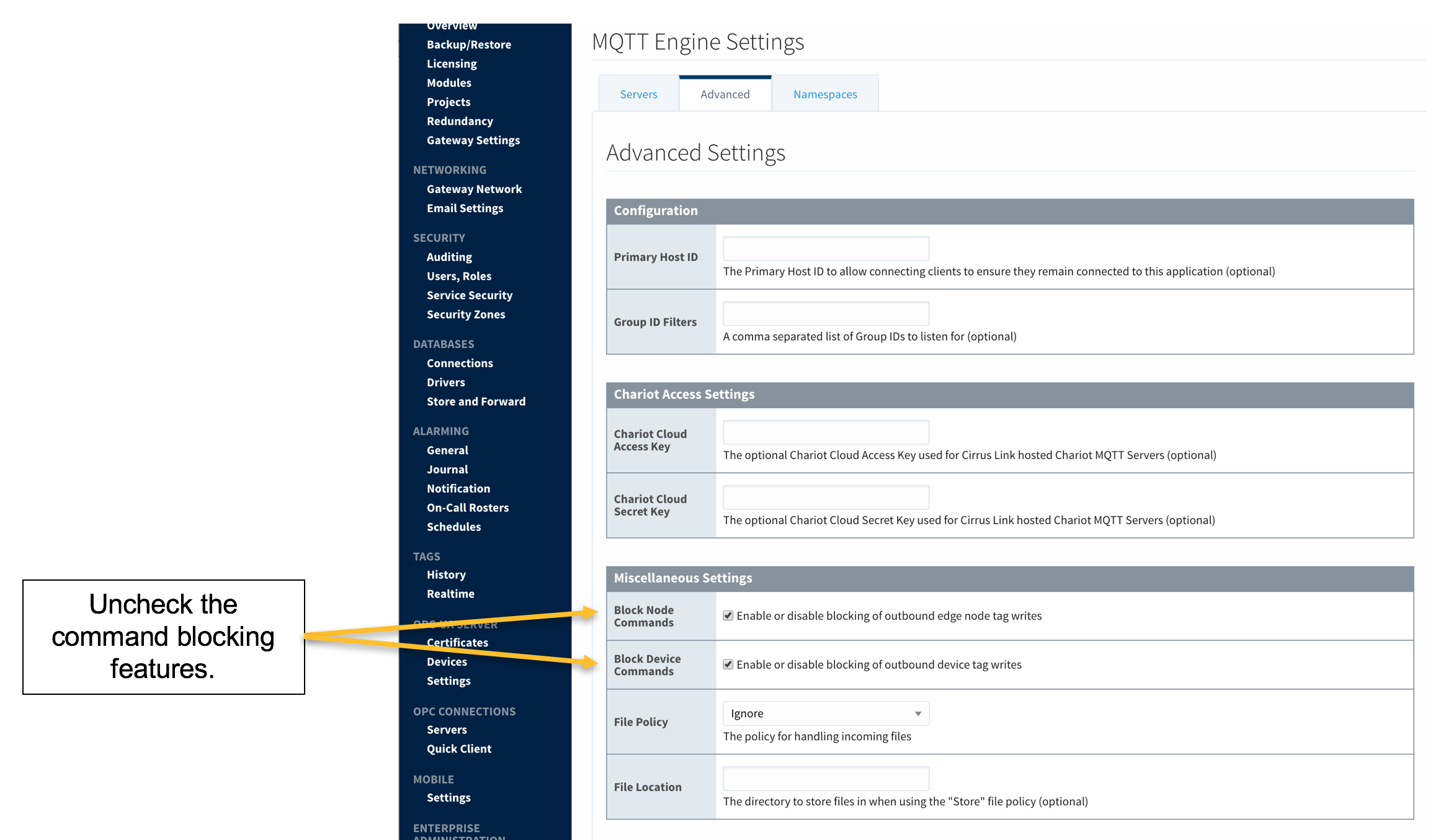
By default, MQTT Distributor, MQTT Engine, and MQTT Transmission are all configured out of the box to be able to connect locally to each other in the exact same architecture of this tutorial. In addition, MQTT Engine will startup with outbound tag writes using the Sparkplug NCMD and DCMD messages blocked. For this tutorial we will want to enable tag writes. This is the only configuration change required for this tutorial. To do so, open the MQTT Engine configuration tab in the Ignition Gateway console and click on the “Advanced Settings” tab. From this configuration screen you can disable command blocking by unchecking “Block Node Commands”, and “Block Device Commands” selections as shown below. After doing so, save the changes.
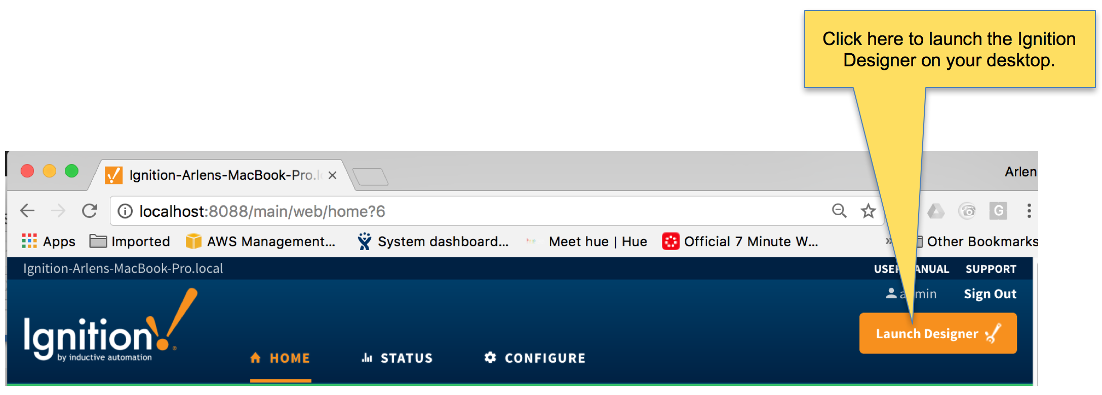
With Ignition running and the Distributor, Engine, and Transmission modules loaded now we can open the Ignition Designer to observe some of the MQTT topology. Regardless of the OS Ignition is running on, there is a “Launch Designer” button on the Ignition Gateway Console. From here you can launch your Designer on any machine. This is shown below. The default credentials for the designer are the same as the Gateway Console, admin/password. Once you have logged into the Designer enter a new project name and open the project. The project name that we used for this tutorial is simply called “Tutorial1”.
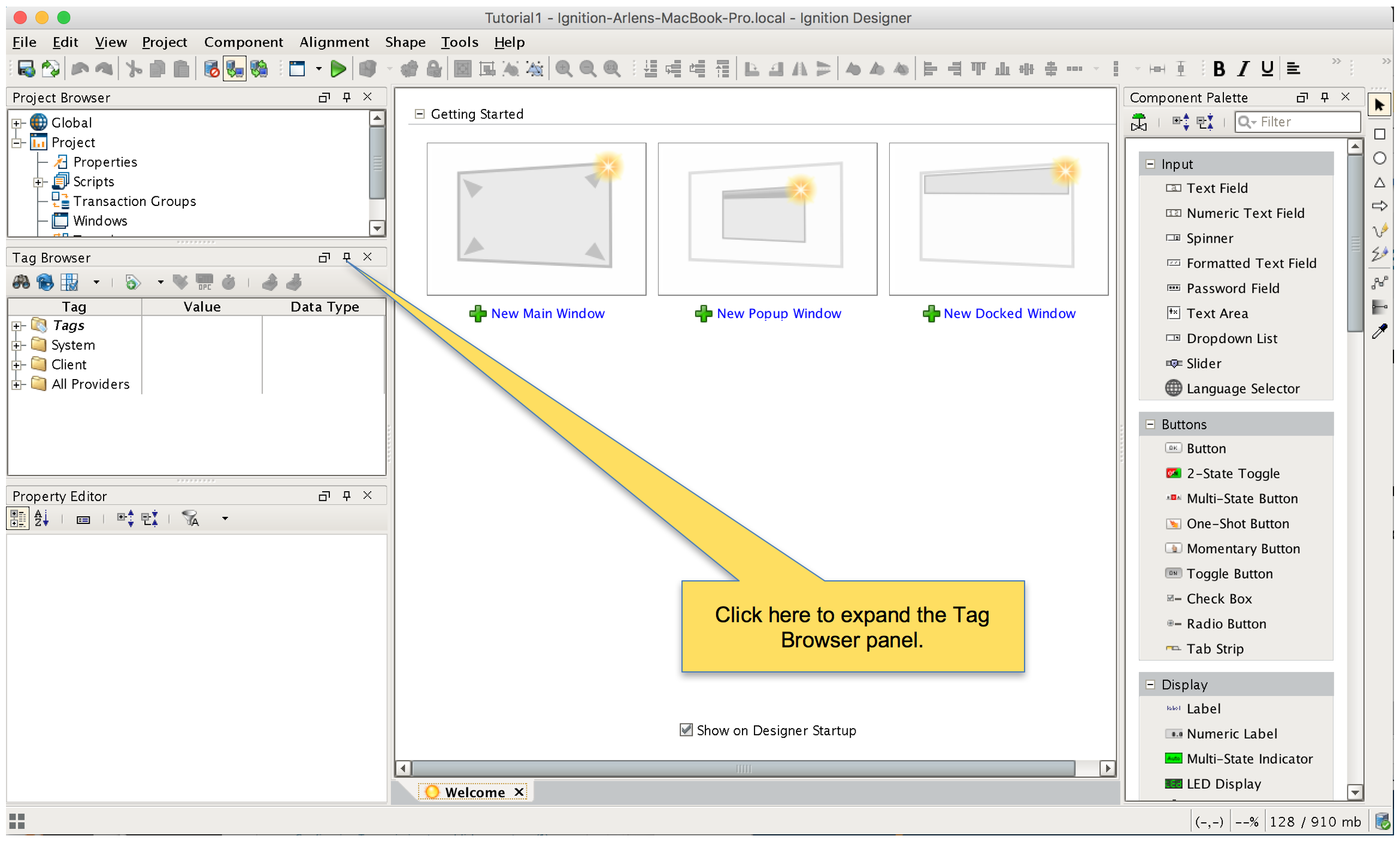
After Designer opens, you will see the default Designer screen as shown below.
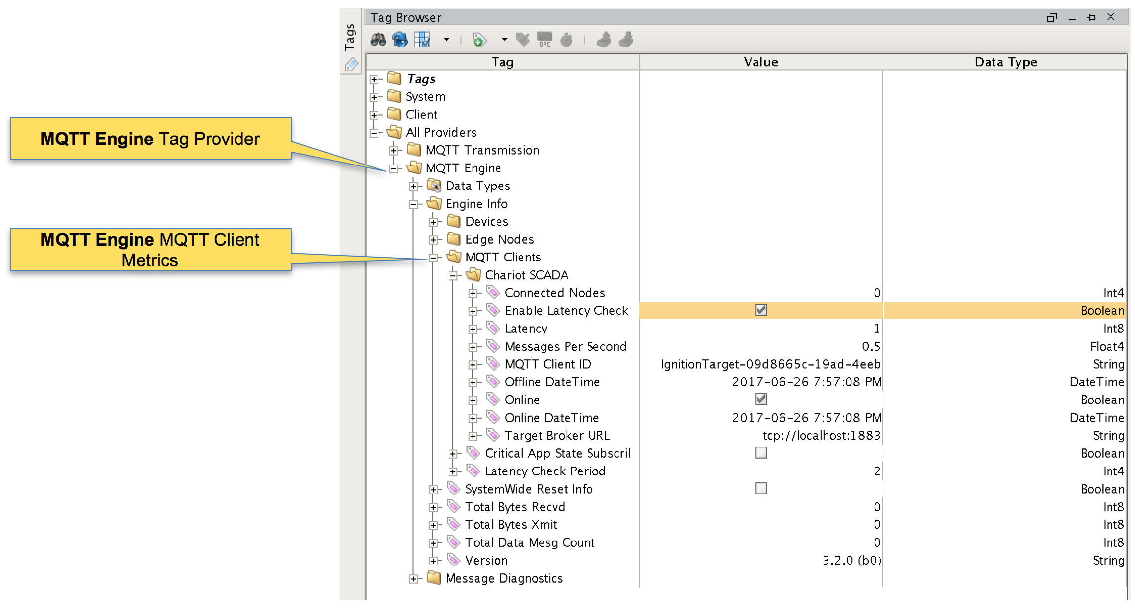
Once the MQTT Engine module is installed in Ignition, a new “Tag Provider” folder is created called “MQTT Engine”. The MQTT Engine folder will contain both process variable tags from field devices as well as metric and diagnostic information from the MQTT infrastructure itself. At this point in the tutorial we can use the tag browser to start looking at the simple MQTT infrastructure we already have running. In the tag structure below using the default MQTT Distributor and MQTT Engine configurations, you can see that the metrics provided for the MQTT Client connection from MQTT Engine to MQTT Distributor.
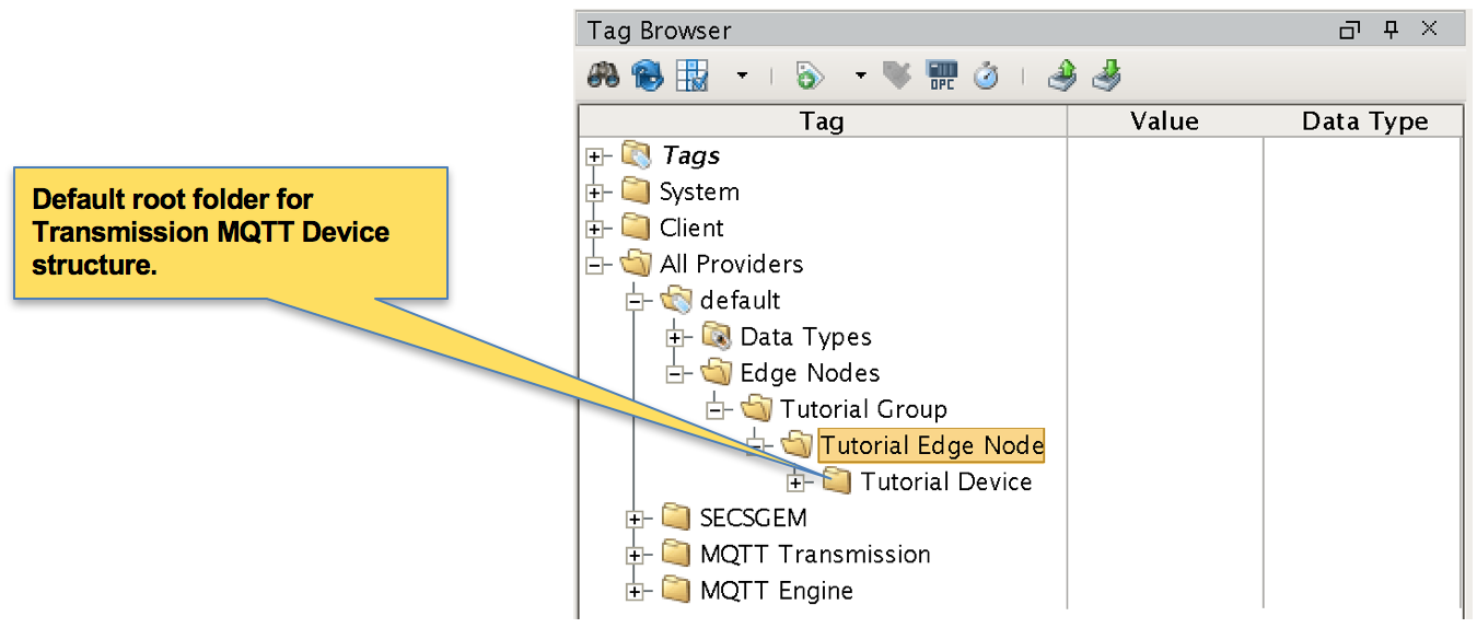
Next, we need to create a folder structure where we will create a virtual MQTT Edge device and some tags to be published by MQTT Transmission. When the Transmission module is installed in Ignition, a folder is automatically created in the Ignition tag structure with the following path:
The is the default folder that Transmission will look at to an MQTT Sparkplug session from. For this tutorial, right click on the Edge Nodes folder and create a new folder called Tutorial Group. Then right click on the Tutorial Group folder and create another new folder called Tutorial Edge Node. Finally, right click on the Tutorial Edge Node folder and create another new folder called Tutorial Device. This folder structure creates the same hierarchy that is described in the Sparkplug B specification of Group ID, Edge ID, and Device ID.
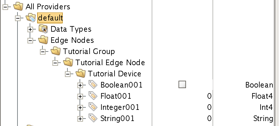
With this folder structure in place, now we can create some memory tags of various data types to publish. Right click on the Tutorial Device folder and select ’New Tag’/’Memory Tag’. In the tag editor change the Name of the tag to “Boolean001”, and change the Data Type to Boolean. Follow this same procedure for new memory tags called “Integer001” of type Integer, “Float001” of type Float, and “String001” of type String. The resulting folder structure should look as follows.
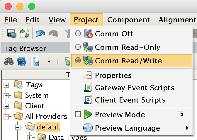
Now that we have a folder structure with some tags we can bring Transmission online. Make sure that the Ignition Designer has read/write communications turned on by selecting Project/Comm Read/Write.
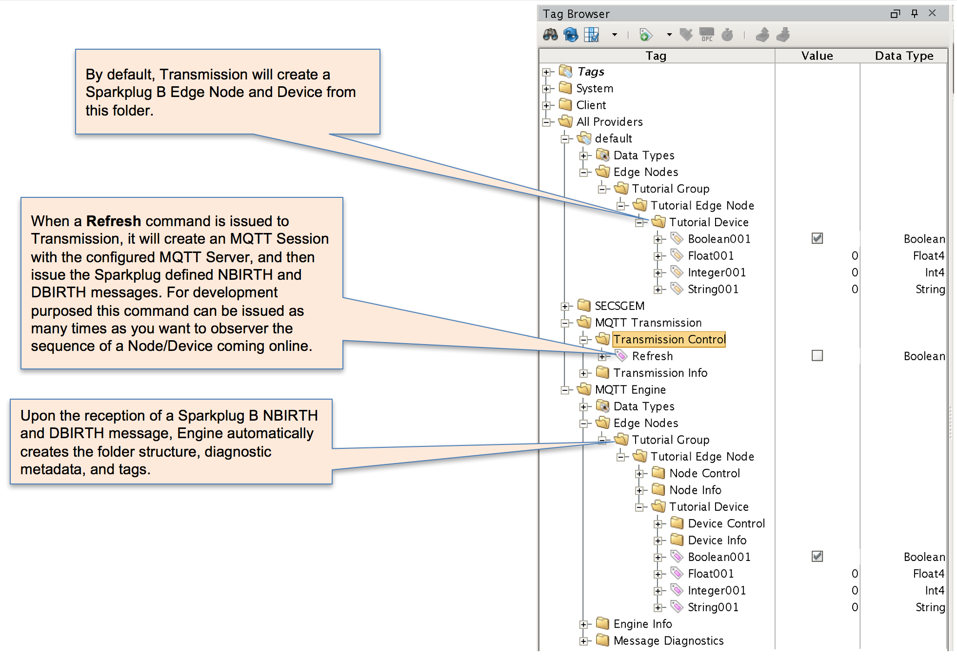
To bring Transmission online with the folder structure we’ve created, open the folder All Providers/MQTT Transmission/Transmission Control and click on the Refresh Boolean. When this happens, following the Sparkplug B specifications, the Transmission module will create an MQTT Session with the MQTT Server and then publish a NBIRTH message followed by a DBIRTH message. Note the Boolean tag will not change to true. This is really a one-shot and as a result, the tag will not change to true.
Then open the All Providers/MQTT Engine/Edge Nodes folder and refresh the Tag Browser. The MQTT Engine MQTT Client has been subscribed to all Sparkplug B messages just waiting for a new Sparkplug B message to arrive. When we enabled Transmission to create a device structure with some tags, Engine was able to receive this message, and then using the Google Protocol Buffers schema, automatically create a new folder structure populated with the tags and metadata around this new device.
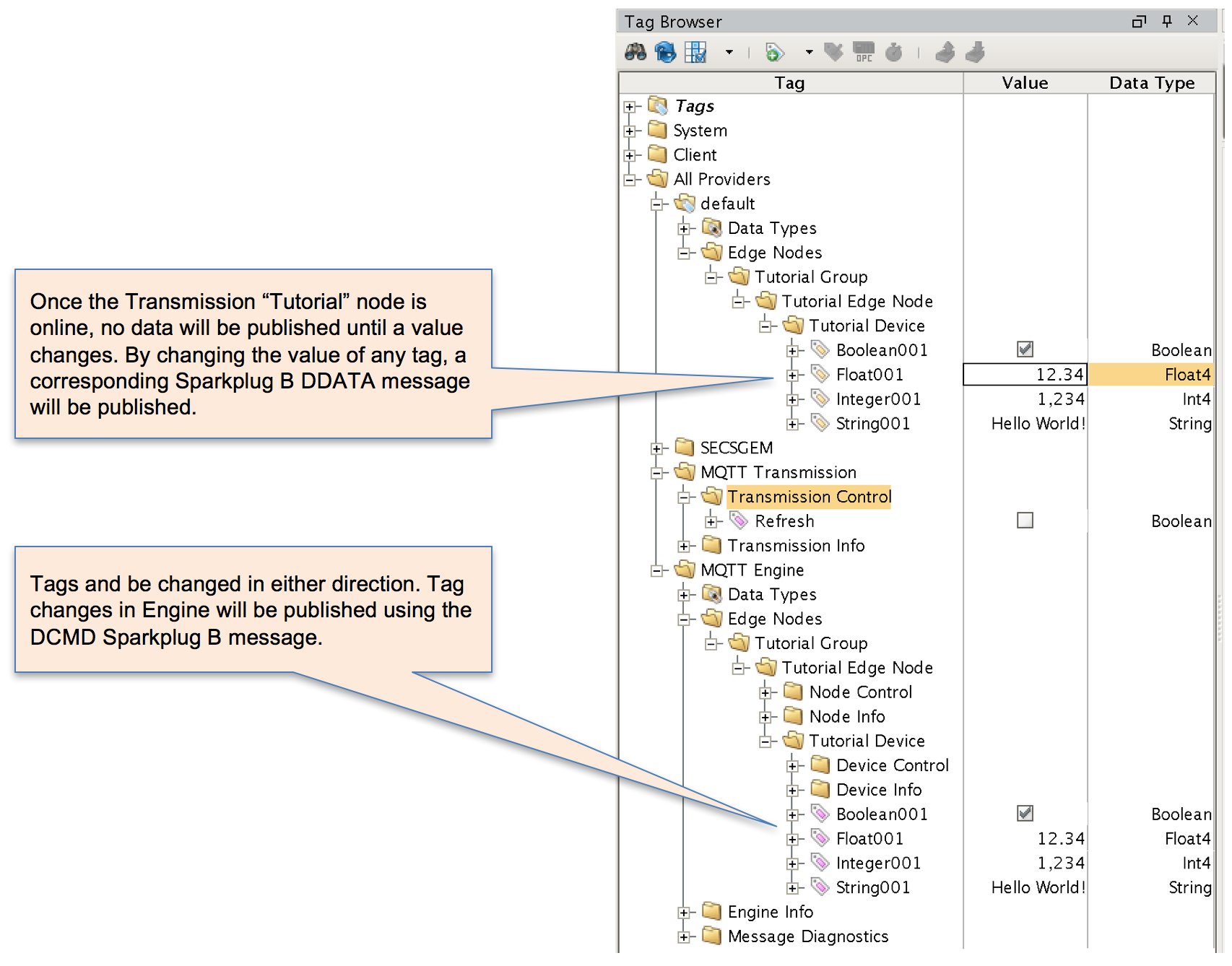
At this point, memory tag values can be changed to generate events which in turn generates new MQTT messages.
At this point you can create new tags in the default tag tree to add additional data points. Any time you add new tags, you must click the 'Transmission Control/Refresh' boolean again to force MQTT Transmission to rescan the tag tree and publish new NBIRTH and DBIRTH messages. It is also important to note that this architecture would not be used in a real world situations. A more realistic yet still simple architecture would be to have MQTT Transmission on one Ignition instance and another Ignition instance which had MQTT Distributor and MQTT Engine installed. This architecture would allow you to replicate tags from one Ignition instance to another using MQTT as the transport. Also, in this example we used memory tags for simplicity. However, OPC tags or other tag types could be used instead in the same manner for more real world solutions.