Versions Compared

Key

  • This line was added.
  • This line was removed.
  • Formatting was changed.

...

  1. Define the global TLP definitions available for all ROC devices in this Ignition instance
  2. Create the base device connection to the ROC
  3. Specify the subset of TLP definitions that this specific ROC uses
  4. Create TLP Template(s) which define groups of TLPs should be polled as a logical group
  5. Create TLP Poll Group(s) which specify the logical parameters associated with a given TLP Template
  6. Use Ignition designer to pull tags into a tag provider

Global TLP Definitions

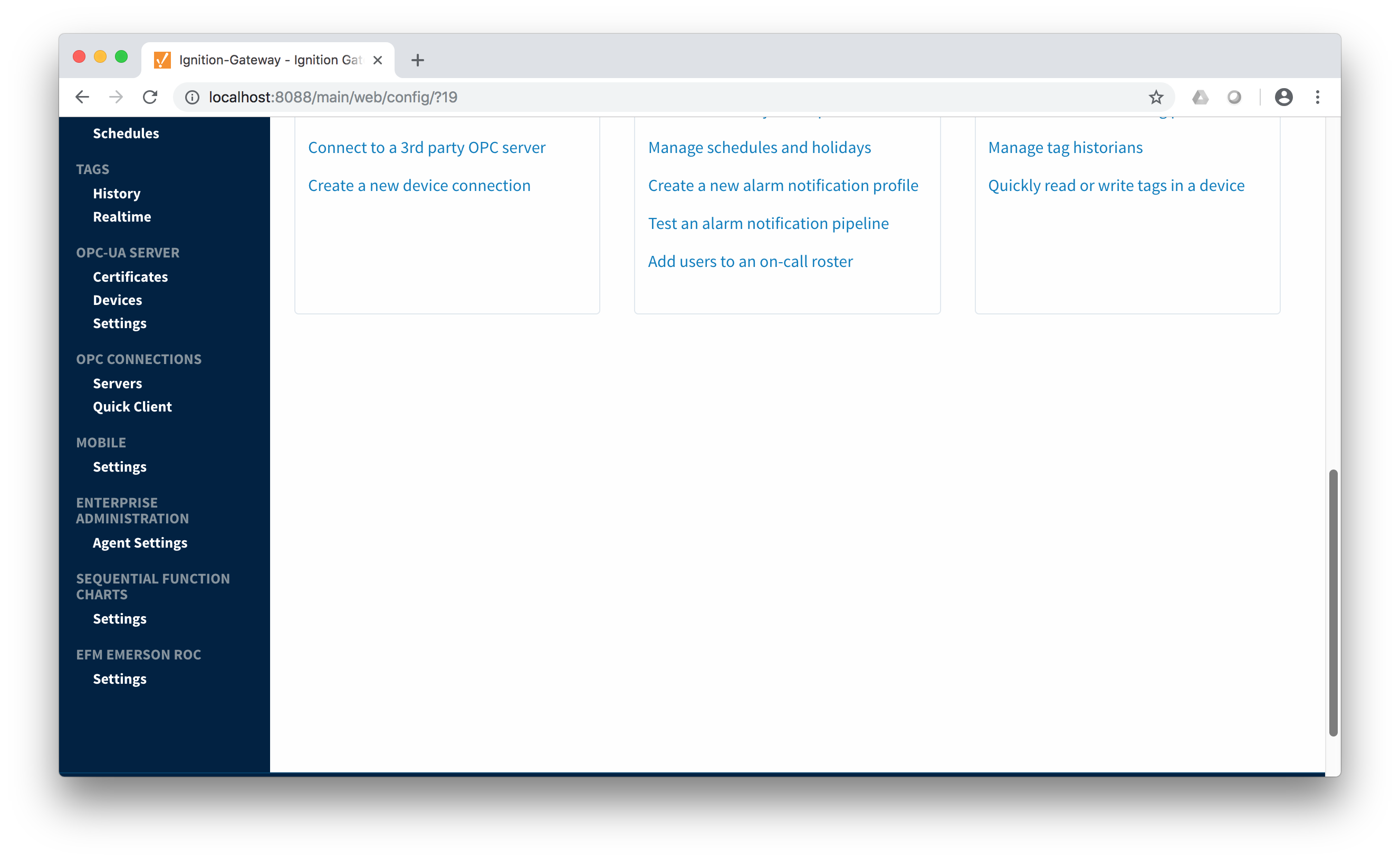
The EFM Emerson ROC driver module provides a configuration section to the Ignition Gateway.  These can be seen in the Configure section of the Ignition Gateway web UI on the left panel near the bottom.  Note this step is required before any EFM Emerson ROC device connections can be define.  Each Emerson ROC device connection will use a subset of these global TLP definitions to operate.

Image Added

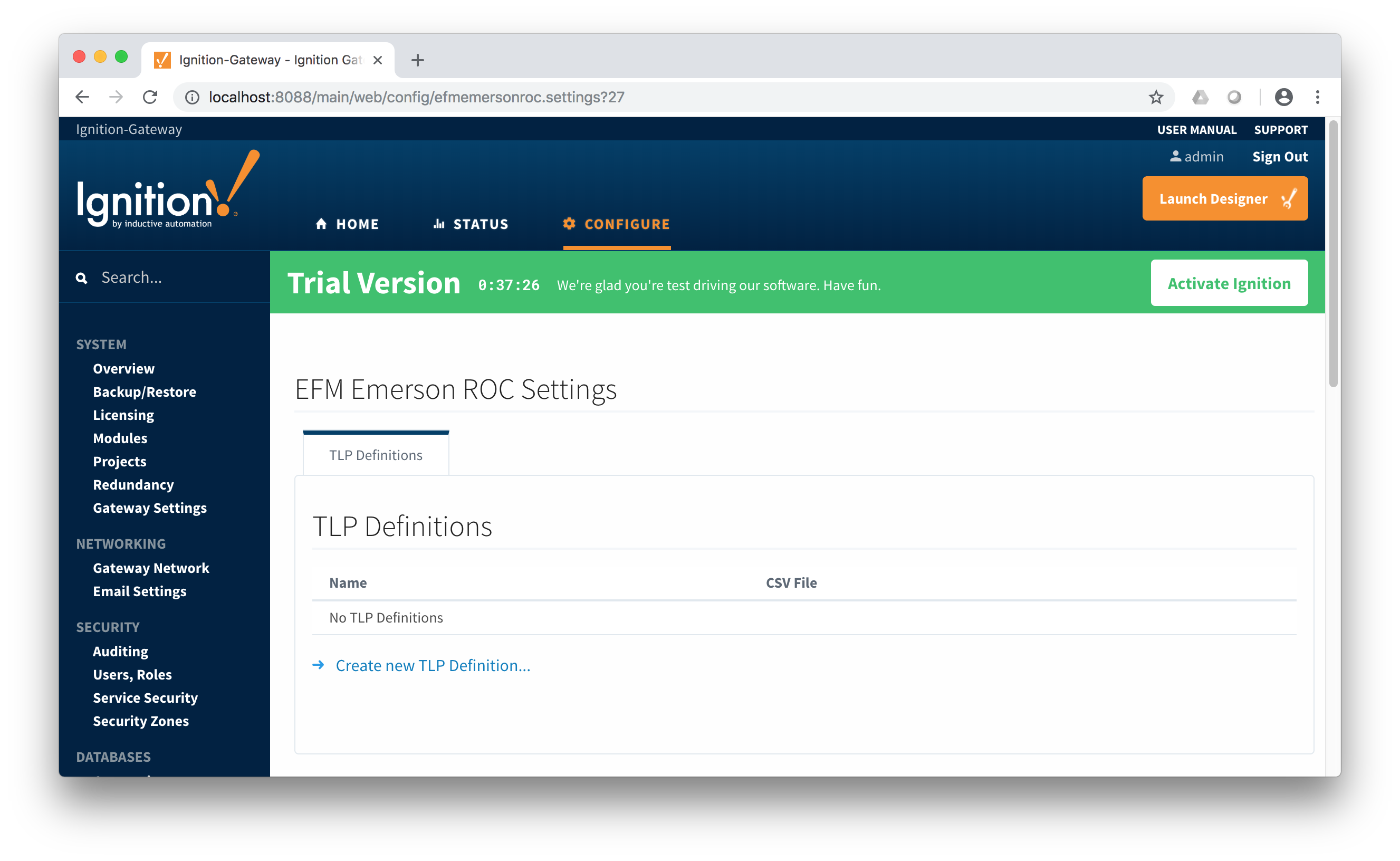
Once in the configuration screen you will see a link to create new global TLP definitions.  Click the link shown below to create a new one.

Image Added

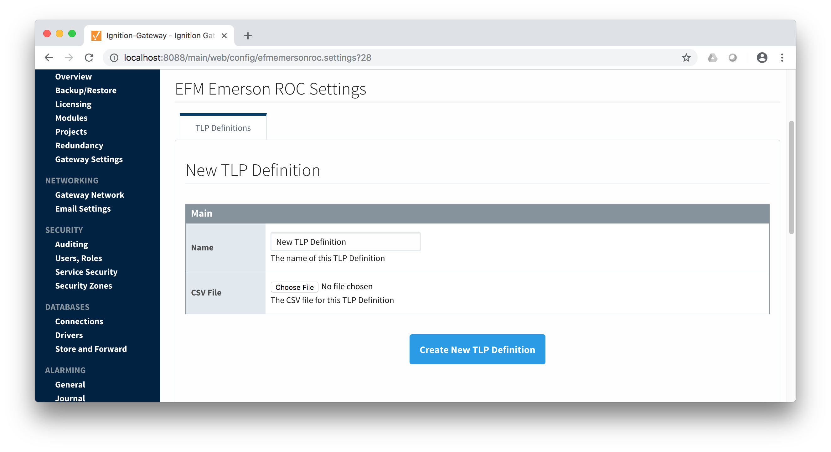
When creating a new global TLP definition only a name and a CSV file needs to be specified.  The name can be any unique name that describes the TLPs included in that CSV file.  They can be device specific TLPs or they can be TLPs associated with a specific user program.

Image Added

The headers of the CSV file must be as follows:

  • Point Type #
    • The 'T' parameter of a TLP - must be an integer
  • Point Type Description
    • A long description of the 'T' parameter
  • Point Type Abbreviation
    • The abbreviation of the 'T' parameter
  • Parameter Number
    • The 'P' parameter of the TLP - must be an integer
  • Parameter Name
    • The descriptive name of the TLP
  • Parameter Description
    • The description of the TLP
  • Parameter Abbreviation
    • This becomes the default tag name of the parameter in Ignition.  It can be changed in any TLP template where it is defined.
  • Access
    • The access value for the TLP.  Must be either R/O or R/W
  • DataType
    • The datatype of the TLP.  Must be one of the following:
      • BIN
        • Binary value
        • 1 byte
        • Ignition Type: Byte
      • AC
        • ASCII String Value
        • Variable number of bytes
        • Ignition Type: String
      • INT8
        • Signed 8-bit Value
        • 1 byte
        • Ignition Type: Short
      • INT16
        • Signed 16-bit Value
        • 2 bytes
        • Ignition Type: Short
      • INT32
        • Signed 32-bit Value
        • 4 bytes
        • Ignition Type: Integer
      • UINT8
        • Unsigned 8-bit Value
        • 1 byte
        • Ignition Type: Short
      • UINT16
        • Unsigned 16-bit Value
        • 2 bytes
        • Ignition Type: Integer
      • UINT32
        • Unsigned 32-bit Value
        • 4 bytes
        • Ignition Type: Long
      • FL
        • 4-byte Floating-Point Value
        • 4 bytes
        • Ignition Type: Float
      • FLP
        • Same as FL
        • 4-byte Floating-Point Value
        • 4 bytes
        • Ignition Type: Float
      • DBL
        • 8-byte Floating-Point Value
        • 8 bytes
        • Ignition Type: Double
      • TIME
        • 4 byte ROC representation of time
      • TLP
        • 3 byte ROC representation of a TLP
      • HOURMINUTE
        • 2 byte ROC representation of hour and minute
      • FLOAT
        • Same as FL
        • 4-byte Floating-Point Value
        • 4 bytes
        • Ignition Type: Float
      • DOUBLE
        • Same as DBL
        • 8-byte Floating-Point Value
        • 8 bytes
        • Ignition Type: Double
      • DT6
        • 6 byte ROC representation of time
  • Length
    • The length of the the value.  For example INT8 is 1, INT16 is 2, for an AC type it is variable and dependent on the specific TLP.


Below is an example of a properly formatted global TLP CSV file:

Point Type #,Point Type Description,Point Type Abbreviation,Parameter Number,Parameter Name,Parameter Description,Parameter Abbreviation,Access,DataType,Length
1,Discrete Inputs,DIN,0,Point Tag ID,,TAG,R/W,AC,10
1,Discrete Inputs,DIN,1,Filter,,FILTER,R/W,UINT8,1
1,Discrete Inputs,DIN,2,Status,,STATUS,R/W,UINT8,1
1,Discrete Inputs,DIN,3,Mode,,MODE,R/W,BIN,1
1,Discrete Inputs,DIN,4,Alarm Code,,ALARM,R/O,BIN,1
1,Discrete Inputs,DIN,5,Accumulated Value,,ACCUM,R/W,UINT32,4
1,Discrete Inputs,DIN,6,On Counter,,ONCTR,R/W,UINT32,4
1,Discrete Inputs,DIN,7,Off Counter,,OFFCTR,R/W,UINT32,4
1,Discrete Inputs,DIN,8,0% Pulse Width,,MINCNT,R/W,INT16,2
1,Discrete Inputs,DIN,9,100% Pulse Width,,MAXCNT,R/W,INT16,2

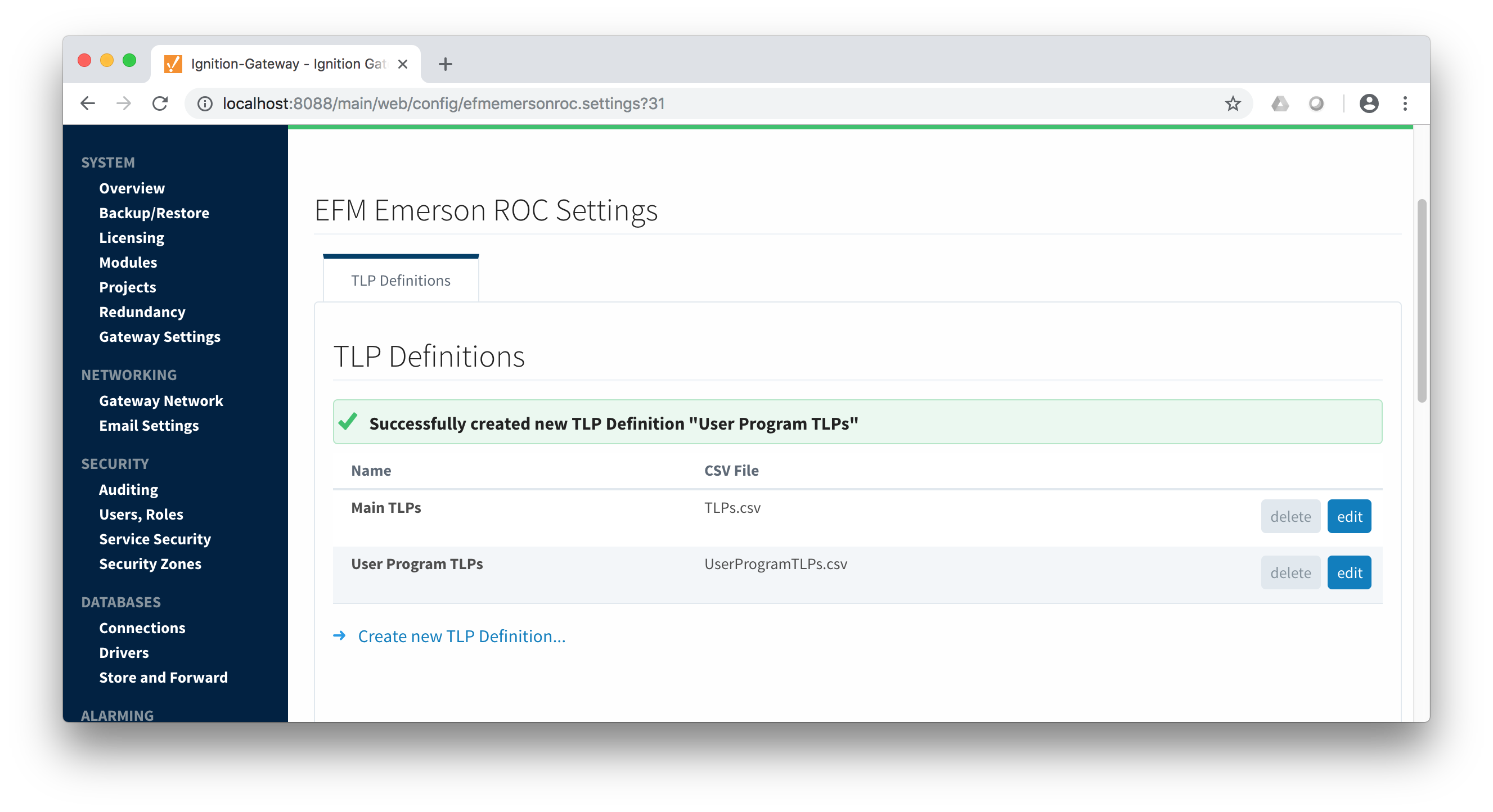
Once you have your properly formatted global TLP definitions they can be uploaded.  Once complete, it will look similar to what is shown below.

Image Added

Creating a Device Connection

...