Versions Compared

Key

  • This line was added.
  • This line was removed.
  • Formatting was changed.

Overview

There are four main types of data that the EFM Emerson ROC driver is capable of getting from an Emerson ROC device.  These are:

  • TLP data
  • Alarm Data
  • Event Data
  • History Data

TLPs are polled at a specified interval based on a poll rate and then made available via the OPC-UA interface.  Alarms, events, and history are made available to MQTT Transmission to be published as immutable record objects to an MQTT server.  Typically these would be received on a central Ignition gateway with the MQTT Engine and MQTT Recorder modules.  Combined those receive the MQTT Sparkplug messages and insert the records into a central DB and be made available to other third party systems or for later use in Ignition.

For the purposes of this document there are some definitions that are explained below.

  • Global TLP Definitions
    • These are the global TLP definitions made available to the Ignition instance.  They are uploaded to the Ignition instance in the form of specificly formation CSV file.  These TLP definitions can then be referenced by a specific instance of a ROC device connection to restrict the TLP definitions to those that apply to that device.  For example, lets say you upload four Global TLP definitions.  Lets say these are ROC800.csv, FLOBOSS107.csv, UserProgram1.csv, and UserProgram2.csv.  With these global definitions there could be differing definitions for any specific T/P combination.  This is only allowed if the differing definitions are in different CSV files.  No one CSV file is allowed to have differing definitions of the same T/P combination.
  • Device TLP Definitions
    • These are a subset of the global TLP definitions that apply to this specific device.  Continuing with the example from above let's say this is a ROC 800 and has User Program 1 installed.  We would select the ROC800.csv and UserProgram1.csv as the TLP definitions that apply to this specific ROC device.
  • TLP Templates
    • TLP templates are groupings of TLPs that represent logical groupings of TLPs.  Generally TLP templates would be created to then can have instances of them created by specifying a poll group with a logical number or the 'L' parameter in a TLP.
  • TLP Poll Groups
    • Poll groups use TLP templates in conjunction with a logical number to create a specific set of TLPs to be polled at a specified poll rate.

There are six basic steps to getting all of the data available in a ROC into Ignition

  1. Define the global TLP definitions available for all ROC devices in this Ignition instance
  2. Create the base device connection to the ROC
  3. Specify the subset of TLP definitions that this specific ROC uses
  4. Create TLP Template(s) which define groups of TLPs should be polled as a logical group
  5. Create TLP Poll Group(s) which specify the logical parameters associated with a given TLP Template
  6. Use Ignition designer to pull tags into a tag provider

Global TLP Definitions

The EFM Emerson ROC driver module provides a EFM Emerson ROC provides a configuration section to the Ignition Gateway .  These that can be seen in the Configure section of the Ignition Gateway web UI on the left panel near the bottom.  Note this step is required before any EFM Emerson ROC device connections can be define.  Each Emerson ROC device connection will use a subset of these global TLP definitions to operate.

Image Removed

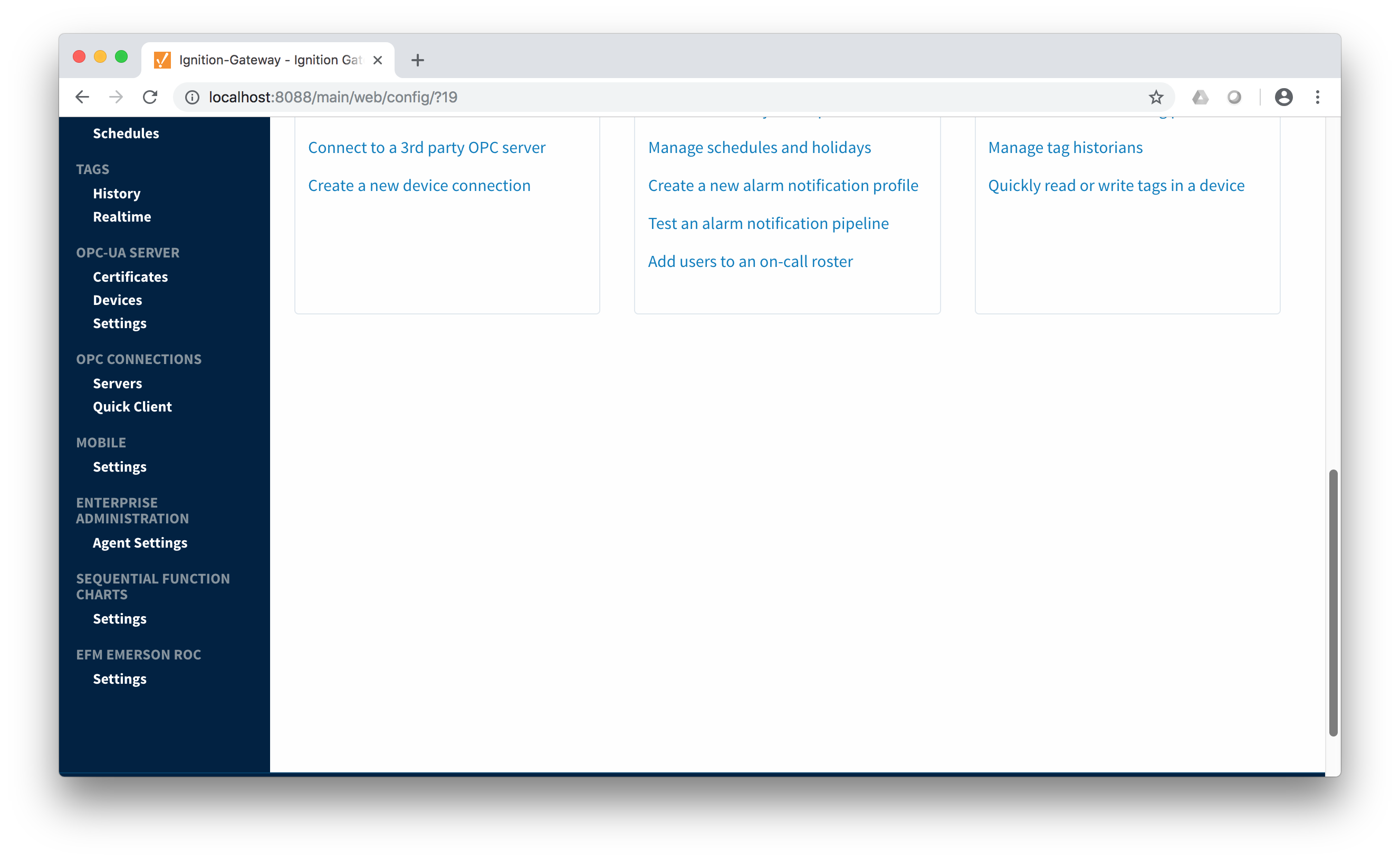
Once in the configuration screen you will see a link to create new global TLP definitions.  Click the link shown below to create a new one.

Image Removed

When creating a new global TLP definition only a name and a CSV file needs to be specified.  The name can be any unique name that describes the TLPs included in that CSV file.  They can be device specific TLPs or they can be TLPs associated with a specific user program.

Image Removed

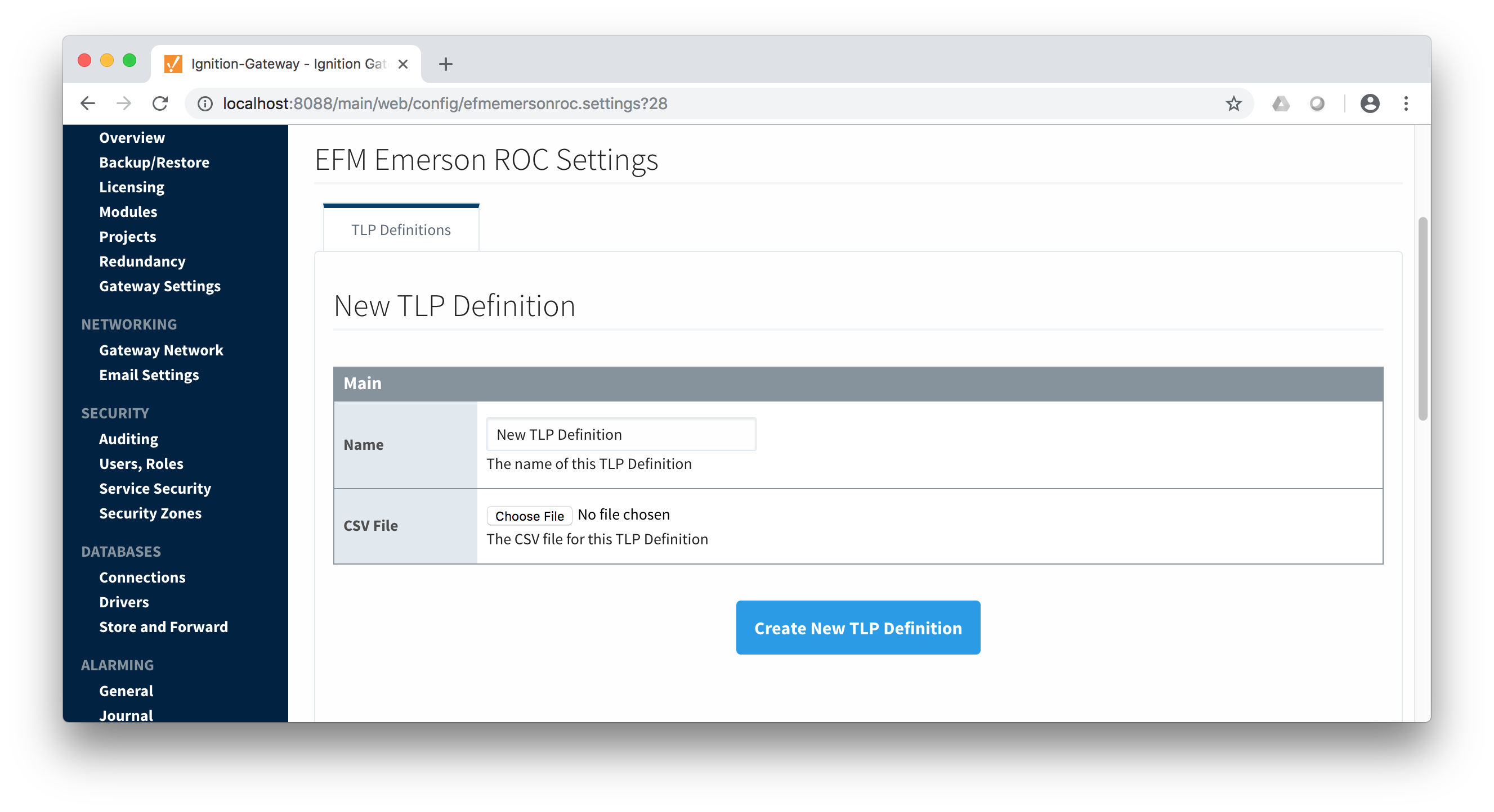
The headers of the CSV file must be as follows:

  • Point Type #
    • The 'T' parameter of a TLP - must be an integer
  • Point Type Description
    • A long description of the 'T' parameter
  • Point Type Abbreviation
    • The abbreviation of the 'T' parameter
  • Parameter Number
    • The 'P' parameter of the TLP - must be an integer
  • Parameter Name
    • The descriptive name of the TLP
  • Parameter Description
    • The description of the TLP
  • Parameter Abbreviation
    • This becomes the default tag name of the parameter in Ignition.  It can be changed in any TLP template where it is defined.
  • Access
    • The access value for the TLP.  Must be either R/O or R/W
  • DataType
    • The datatype of the TLP.  Must be one of the following:
      • BIN
        • Binary value
        • 1 byte
        • Ignition Type: Byte
      • AC
        • ASCII String Value
        • Variable number of bytes
        • Ignition Type: String
      • INT8
        • Signed 8-bit Value
        • 1 byte
        • Ignition Type: Short
      • INT16
        • Signed 16-bit Value
        • 2 bytes
        • Ignition Type: Short
      • INT32
        • Signed 32-bit Value
        • 4 bytes
        • Ignition Type: Integer
      • UINT8
        • Unsigned 8-bit Value
        • 1 byte
        • Ignition Type: Short
      • UINT16
        • Unsigned 16-bit Value
        • 2 bytes
        • Ignition Type: Integer
      • UINT32
        • Unsigned 32-bit Value
        • 4 bytes
        • Ignition Type: Long
      • FL
        • 4-byte Floating-Point Value
        • 4 bytes
        • Ignition Type: Float
      • FLP
        • Same as FL
        • 4-byte Floating-Point Value
        • 4 bytes
        • Ignition Type: Float
      • DBL
        • 8-byte Floating-Point Value
        • 8 bytes
        • Ignition Type: Double
      • TIME
        • 4 byte ROC representation of time
      • TLP
        • 3 byte ROC representation of a TLP
      • HOURMINUTE
        • 2 byte ROC representation of hour and minute
      • FLOAT
        • Same as FL
        • 4-byte Floating-Point Value
        • 4 bytes
        • Ignition Type: Float
      • DOUBLE
        • Same as DBL
        • 8-byte Floating-Point Value
        • 8 bytes
        • Ignition Type: Double
      • DT6
        • 6 byte ROC representation of time
  • Length
    • The length of the the value.  For example INT8 is 1, INT16 is 2, for an AC type it is variable and dependent on the specific TLP.

Below is an example of a properly formatted global TLP CSV file:

Point Type #,Point Type Description,Point Type Abbreviation,Parameter Number,Parameter Name,Parameter Description,Parameter Abbreviation,Access,DataType,Length
1,Discrete Inputs,DIN,0,Point Tag ID,,TAG,R/W,AC,10
1,Discrete Inputs,DIN,1,Filter,,FILTER,R/W,UINT8,1
1,Discrete Inputs,DIN,2,Status,,STATUS,R/W,UINT8,1
1,Discrete Inputs,DIN,3,Mode,,MODE,R/W,BIN,1
1,Discrete Inputs,DIN,4,Alarm Code,,ALARM,R/O,BIN,1
1,Discrete Inputs,DIN,5,Accumulated Value,,ACCUM,R/W,UINT32,4
1,Discrete Inputs,DIN,6,On Counter,,ONCTR,R/W,UINT32,4
1,Discrete Inputs,DIN,7,Off Counter,,OFFCTR,R/W,UINT32,4
1,Discrete Inputs,DIN,8,0% Pulse Width,,MINCNT,R/W,INT16,2
1,Discrete Inputs,DIN,9,100% Pulse Width,,MAXCNT,R/W,INT16,2

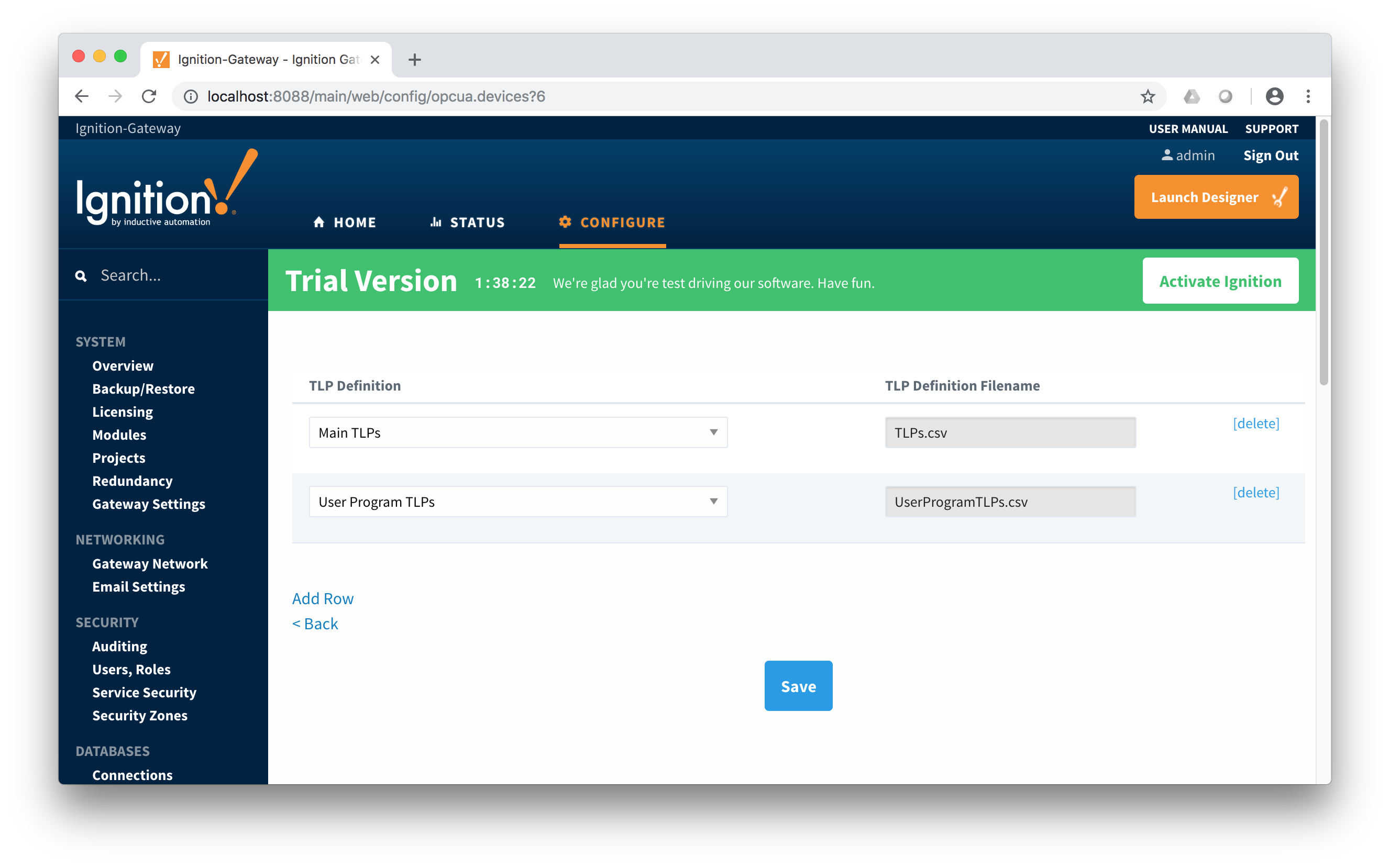
Once you have your properly formatted global TLP definitions they can be uploaded.  Once complete, it will look similar to what is shown below.

Image Removed

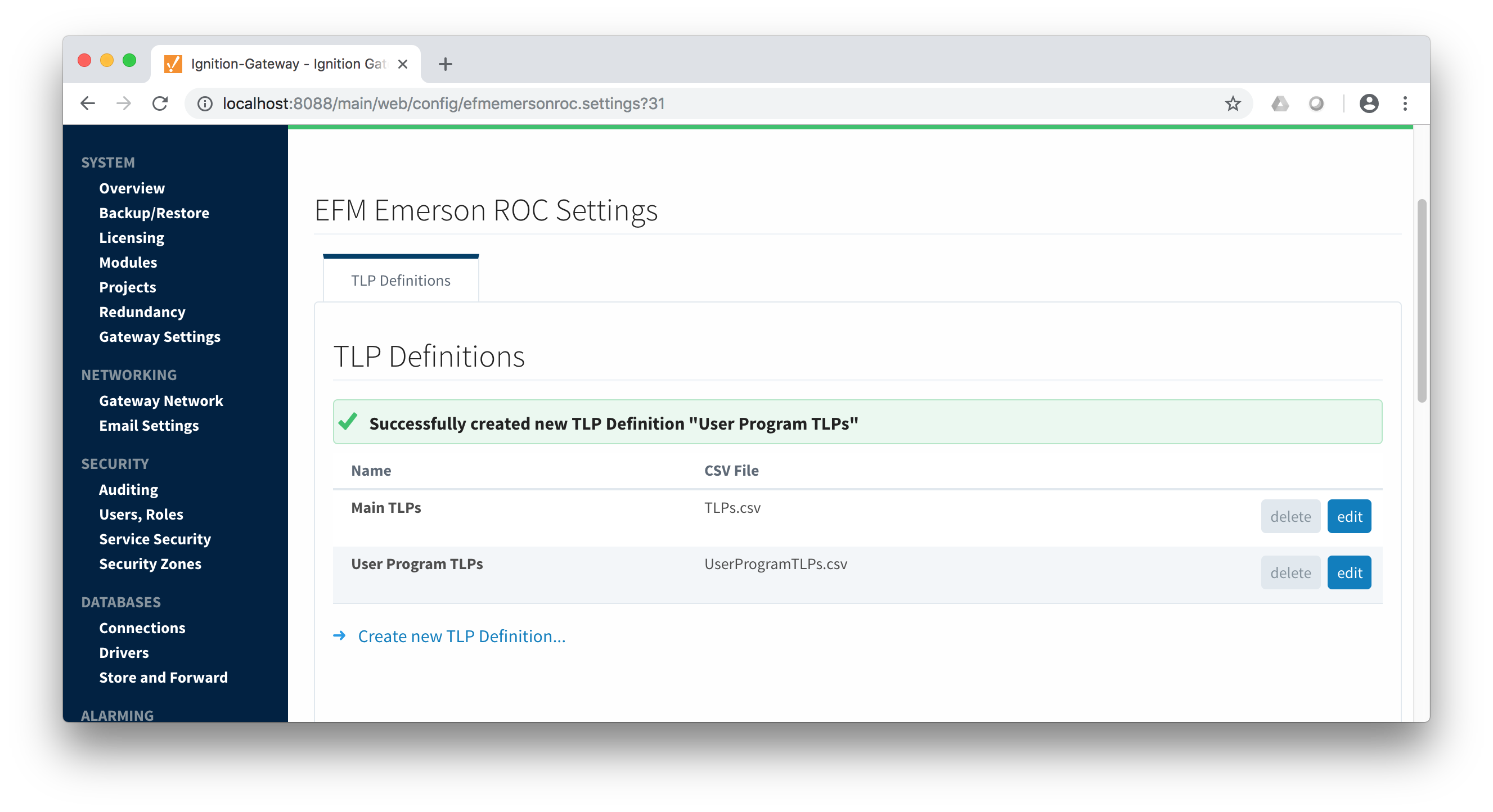
At this point device connections can be created using these global TLP definitions.

Creating a Device Connection

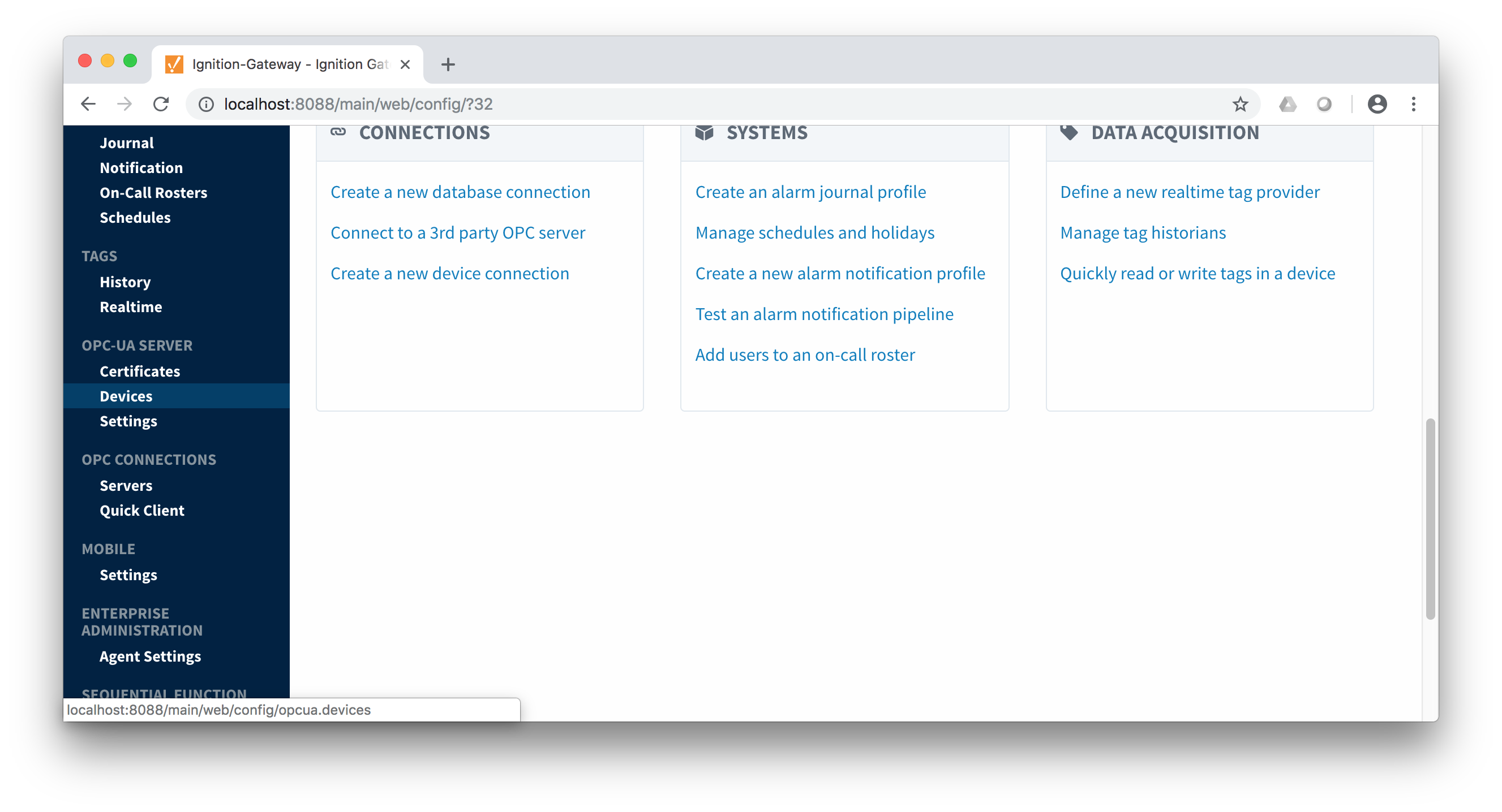
Configuring an Emerson ROC device connection is done as is with any other driver using the OPC-UA interface.  Begin by clicking the Configure tab at the top of the Ignition Gateway web UI and scrolling down to the OPC-UA Server's Devices section and clicking it as shown below.

Image Removed

. There is one configuration page - 'Settings'

Figure 1. EFM Emerson ROC Module Configuration.Image Added

Settings

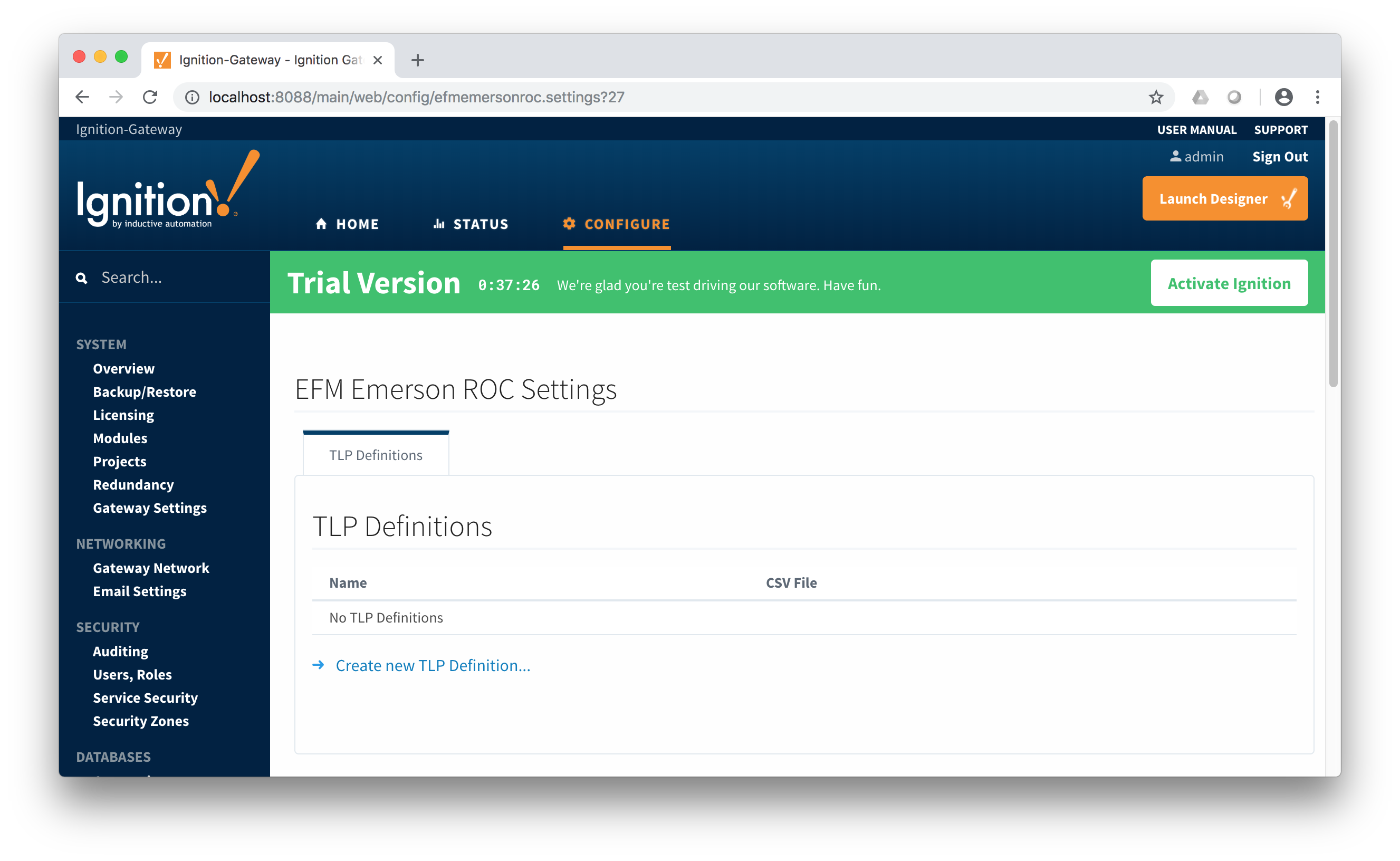
The EFM Emerson ROC Settings configuration page allows user to create TLP Definitions as shown below:

Figure 2. EFM Emerson ROC Settings -- TLP Definitions.Image Added

New TLP Definitions can be created by following the 'Create new TLP Definition' link as shown below:

Figure 3. EFM Emerson ROC Settings -- New TLP Definition.Image Added

Main Properties

  • Name
    • This is the friendly name of the TLP Definition being created
  • CSV File
    • Click the 'Browse' button to select CSV file for this TLP Definition

Click here to download the Cirrus Link default TLP and mapping files - Note these need to be thoroughly tested and reviewed in your application before they are put into production.

The downloaded zip file contains:


     FB107-TLPs-V1_0.csv

     FB107-Meter_Configuration_Mapping-V1_0.csv

     FB107-Orifice_Turbine_Meter_Periodic_History_Mapping-V1_0.csv


     ROC800-TLPs-V1_0.csv

     ROC800-Meter_Configuration_Mapping-V1_0.csv

     ROC800-Orifice_Turbine_Meter_Periodic_History_Mapping-V1_0.csv


     UserProgram-TLPs-V1_0.csv

Emerson ROC Device Connection

Device connection for Emerson ROC module can be configured via OPC-UA SERVER.

Figure 4 -- Emerson ROC Device Connection.Image Added

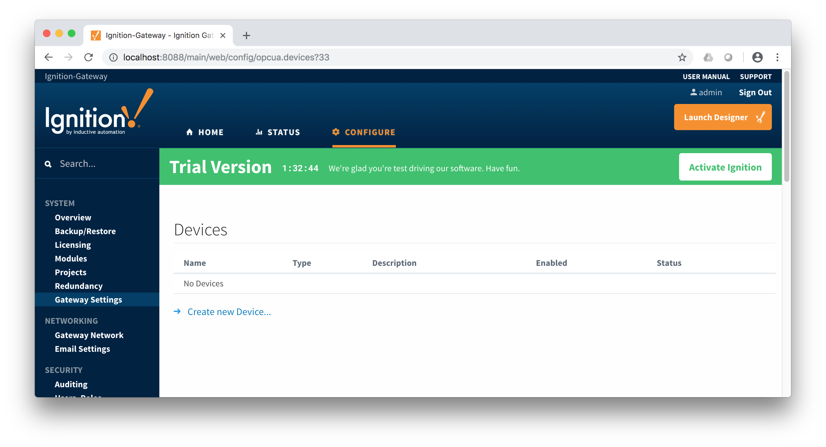
Selecting 'Devices' opens respective configuration page as shown below:

Image Added

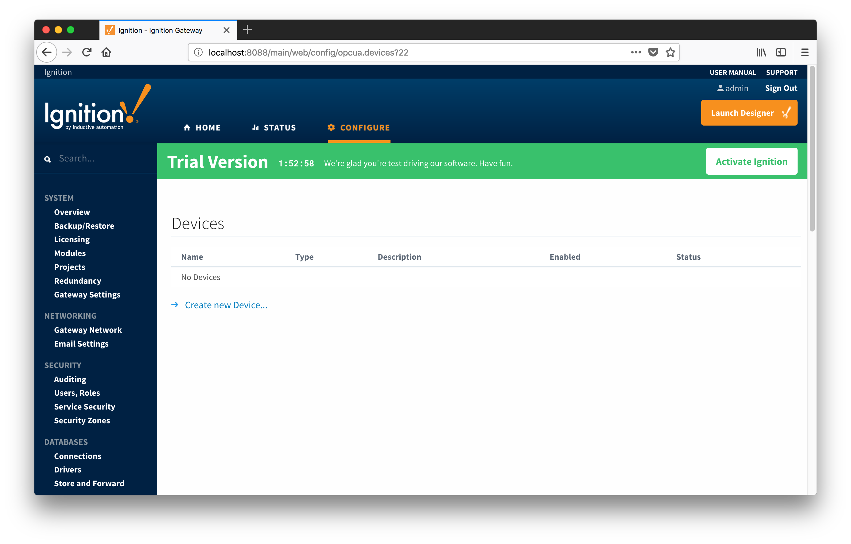
New Emerson ROC device can be created by following Once done you will see the following.  Click the 'Create new Device...' link to create the and choosing 'EFM Emerson ROC device connection.

Image Removed
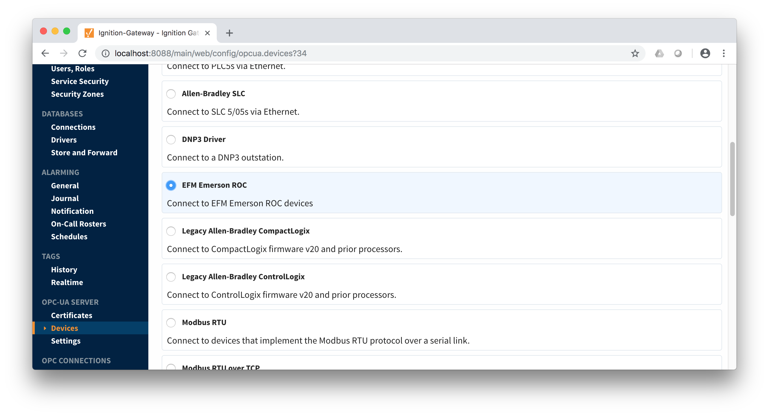
After clicking the 'Create new Device...' link you will see the following.  Select the 'EFM Emerson ROC' and click 'Next' at the bottom of the page.

Image Removed

When creating a new device you will see the following.

Image Removed

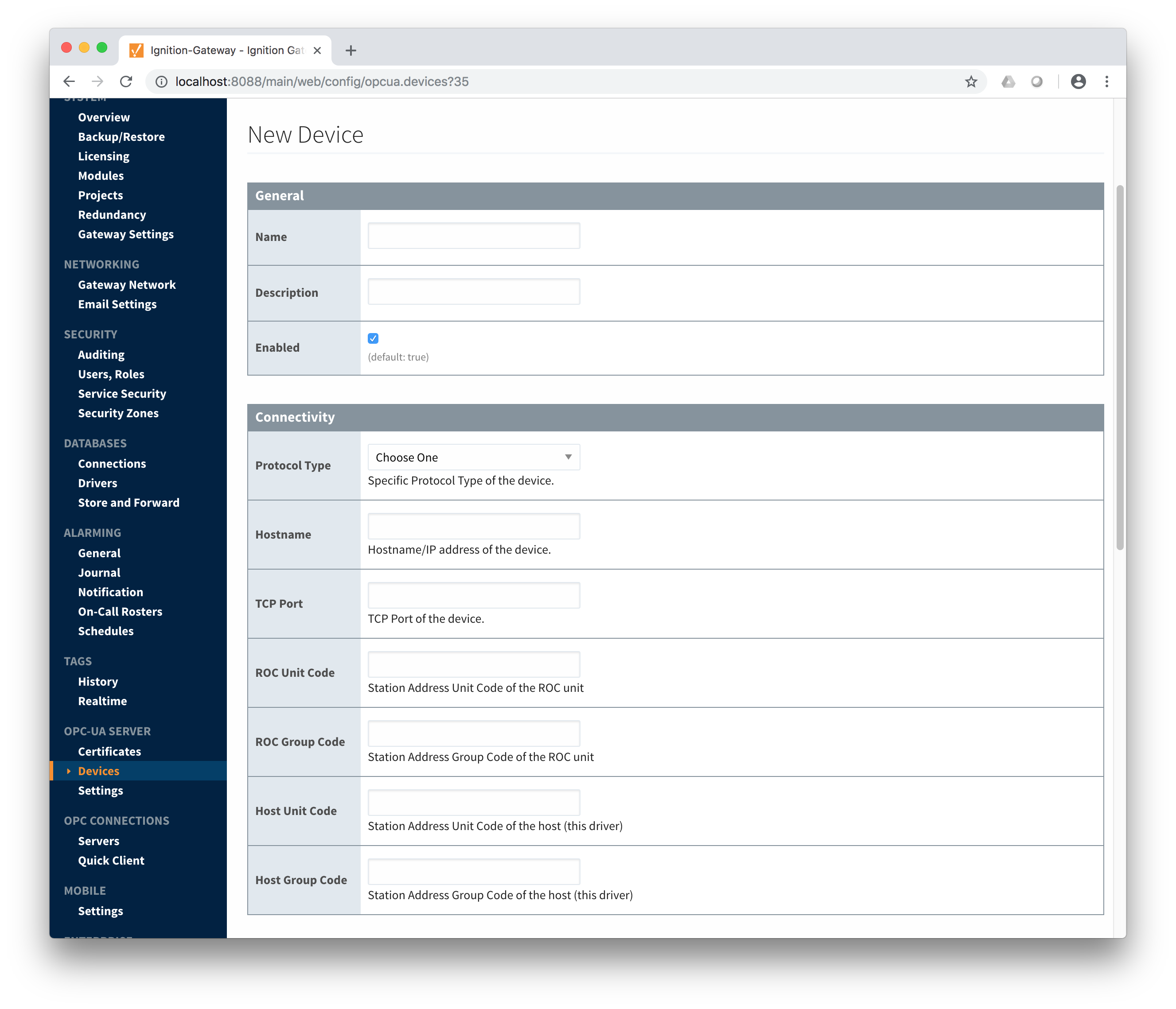
The following describes the parameters that can be set here.

' device as shown below:

Figure 6. EFM Emerson ROC Device Connection -- Choose Device Type.Image Added

This opens the 'New Device' configuration mage for EFM Emerson ROC Device:

Figure 7. EFM Emerson ROC Device Connection -- Configuring New Device.Image Added

General

  • Name
    • Device name
  • Description
    • Device description
  • Enabled
    • Device
    General
    • Name
      • The unique name of this device
    • Description
      • The description of this device
    • EnabledWhether or not this device is enabled

Connectivity

  • Protocol Type
    • Specific Protocol Type of the device
      • ROC
      • ROC_PLUSEither ROC or ROC Plus depending on the type of device
  • Hostname
    • The Hostname or IP address or hostname of the Emerson ROC device
  • TCP Port
    • The TCP port Port of the Emerson ROC device is listening on.
  • ROC Unit Code
    • The unit code assigned to Station Address Unit Code of the ROC deviceunit
  • ROC Group Code
    • The group code assigned to Station Address Group Code of the ROC deviceunit
  • Host Unit Code
    • The host unit code assigned to the Ignition instanceStation Address Unit Code of the host (this driver)
  • Host Group Code
    • The host group code assigned to the Ignition instanceStation Address Group Code of the host (this driver)

Records

  • Alarm Scan Rate
    • The rate ( in seconds ) at which the Emerson ROC driver should check for new alarmsthat alarm records are scanned
    • Set to -1 to disable alarm scanning (default)
  • Event Scan Rate
    • The rate ( in seconds ) at which the Emerson ROC driver should check for new eventsthat event records are scanned
    • Set to -1 to disable event scanning (default)
  • Minute History Scan Rate
    • The rate (in seconds) at which the Emerson ROC driver should check for new minute historyin seconds that minute history records are scanned
    • Set to -1 to disable minute history scanning (default)
  • Periodic History Scan Rate
    • The rate (in seconds) at which the Emerson ROC driver should check for new periodic historyin seconds that periodic history records are scanned
    • Set to -1 to disable periodic history scanning (default)
  • Daily History Scan Rate
    • The rate ( in seconds ) at which the Emerson ROC driver should check for new that daily history records are scanned
    • Set to -1 to disable daily history scanning (default)

Sparkplug

  • Group ID
    • The Sparkplug Group ID which should be used when publishing events, alarms, and history.  The Sparkplug Group ID, Edge Node ID, and Device ID must exist in MQTT Transmission in order for records to be published.An ID representing a logical grouping of Edge Nodes and Devices
  • Edge Node ID
    • The Sparkplug Edge Node ID which should be used when publishing events, alarms, and history.  The Sparkplug Group ID, Edge Node ID, and Device ID must exist in MQTT Transmission in order for records to be published.An ID representing an Edge or Network (EoN) Node
  • Device ID
    • The Sparkplug Device ID which should be used when publishing events, alarms, and history.  The Sparkplug Group ID, Edge Node ID, and Device ID must exist in MQTT Transmission in order for records to be published.

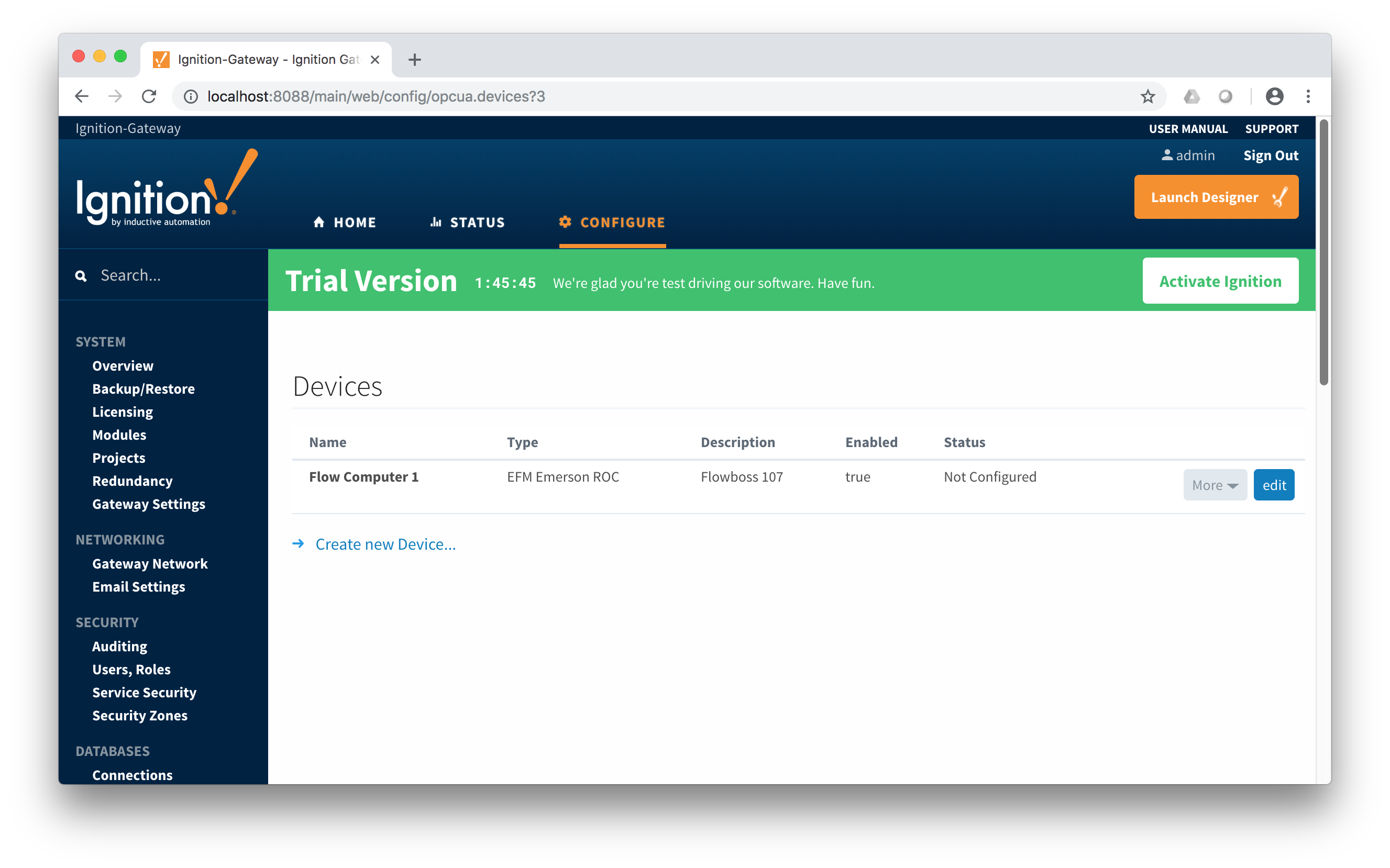
Once the device is created, you should see it is listed in the devices section with a status of 'Not Configured' as shown below.  The next sections will show the rest of the configuration that will complete the setup.

Image Removed

Specifying TLP Definitions for a Device

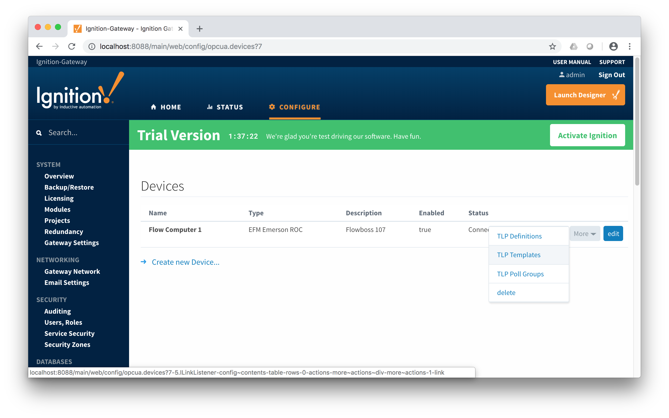
With the device now established the specific global TLP templates that are appropriate for this device must be associated with it.  Do so by clicking the 'More' drop-down button and selecting 'TLP Definitions' as shown below.

Image Removed

You should now see an empty list of TLP definitions associated with this specific device.  Click the 'Add Row' link that is shown below.

Image Removed

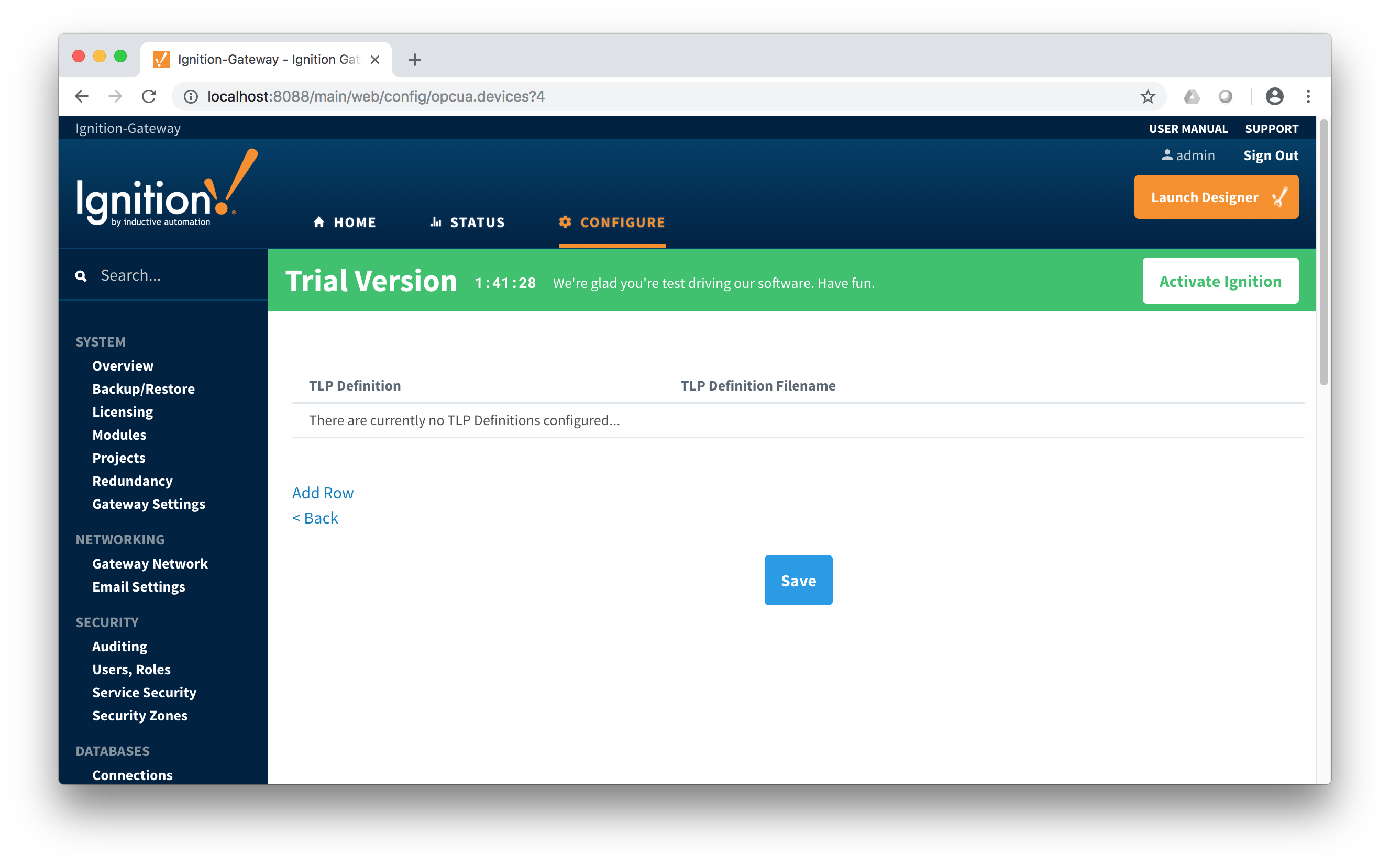
This will show a new TLP definition with a select box to allow you to select which global TLP definition you want to associate with this device.  Add as many as are appropriate for your device as shown below.

Image Removed

When complete, save the list and you will be taken back to the Devices list.

Creating TLP Templates for a Device

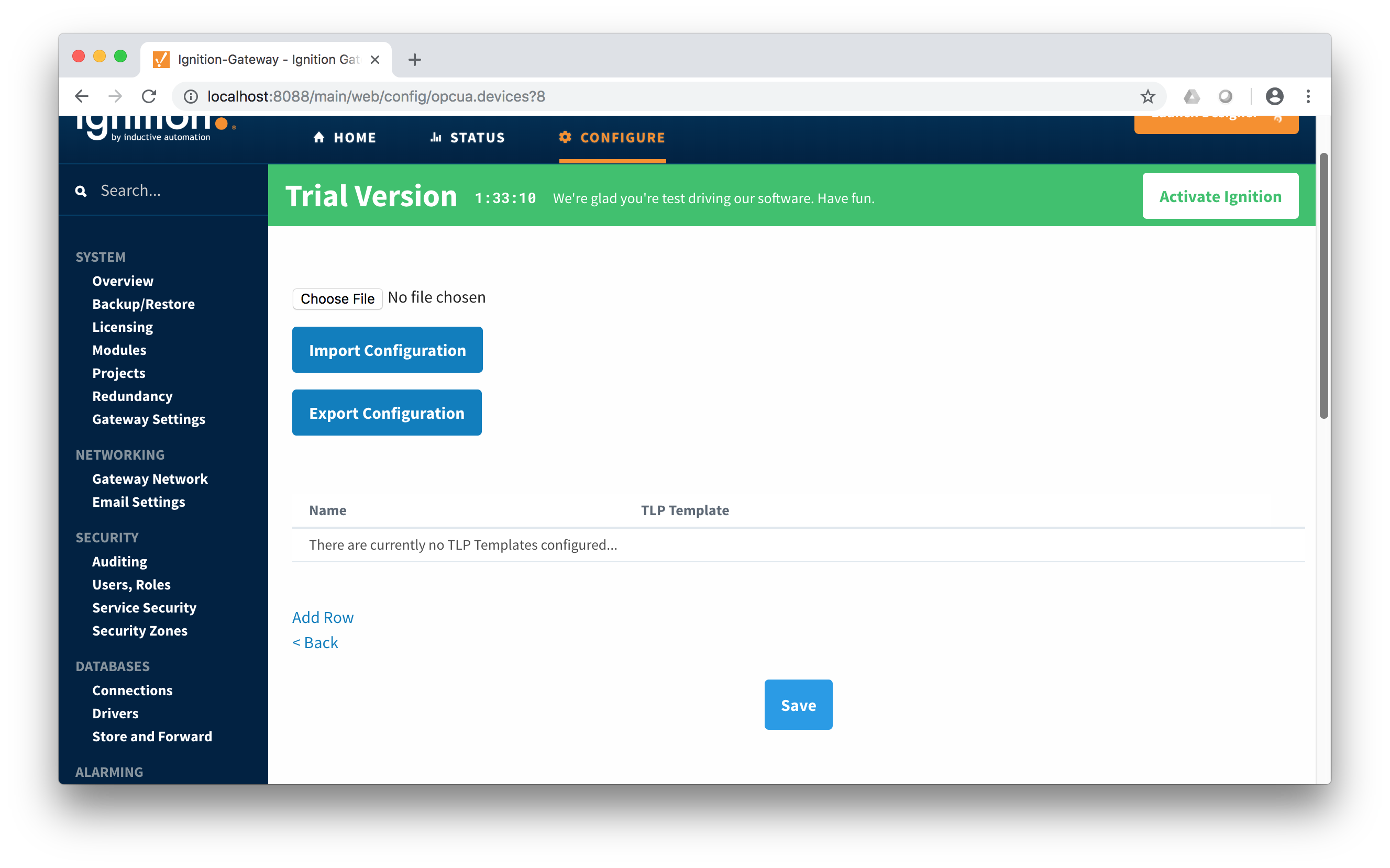
With the TLP definitions now defined for this device we can create some TLP templates to allow creation of TLP poll groups.  You should also note at this point that the Status shows 'Connected' for the device.  To create a TLP template, click on the 'More' drop-down menu and select 'TLP Templates' as shown below.

Image Removed

To add a TLP template, click the 'Add Row' link shown below.

Image RemovedAt this point you can give the new TLP template a name that makes sense. Then click the 'Edit TLP Template Contents' link next to the name field shown below.

Image Removed

At this point you can begin adding new TLPs by clicking the 'Add Row' link shown below.

Image Removed

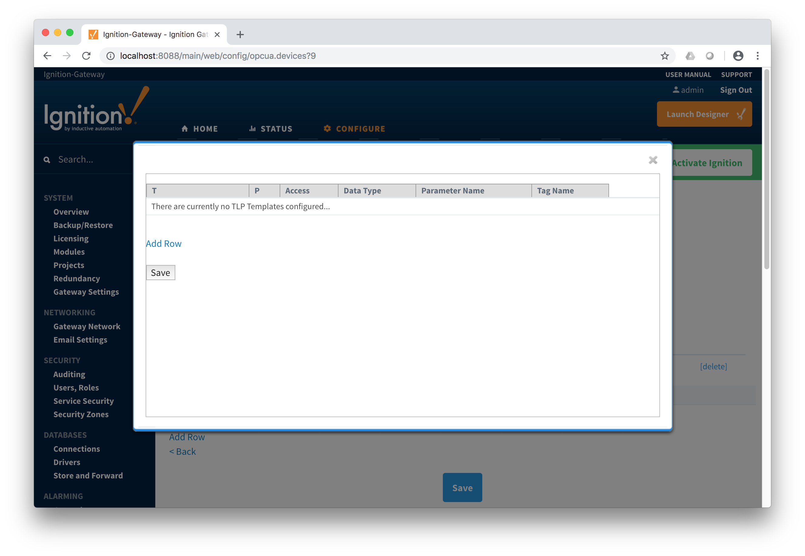
The TLPs available to be added are based on the TLP definitions that have been made available to this specific device.  Add TLPs that make sense to be grouped together in a logical group.  When complete you should see something similar to what is shown below.  Click the 'Save' button.

Image Removed

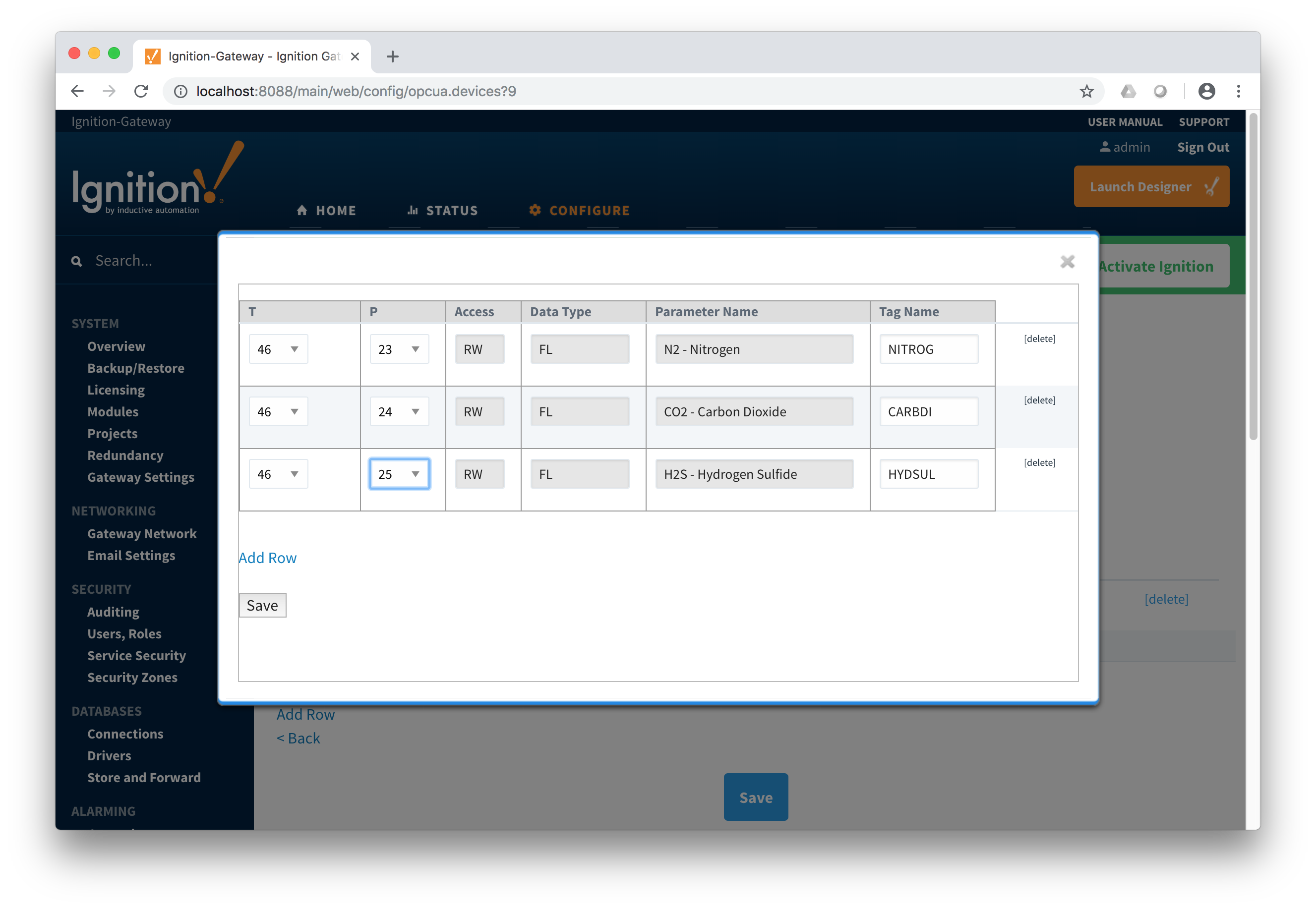
Note there are six fields available for each row of which only three can be modified.  These are:

  • T
    • The 'T' parameter of the TLP
  • P
    • The 'P' parameter of the TLP
  • Access
    • The access for this value - either RO for 'read only' or RW for 'read/write'
    • Cannot be modified here.  It is defined in the global TLP definition CSV file.
  • Data Type
    • The data type for this TLP
    • Cannot be modified here.  It is defined in the global TLP definition CSV file.
  • Parameter Name
    • The descriptive name of this TLP
    • Cannot be modified here.  It is defined in the global TLP definition CSV file.
  • Tag Name
    • The tag name that will show up in Ignition for this TLP.
    • The default value comes from 'Parameter Abbreviation' of the global TLP definition CSV file.  It can be changed here to any value.

Add as many templates as you'd like, then click the 'Save' button at the bottom of the page shown below.

Image Removed
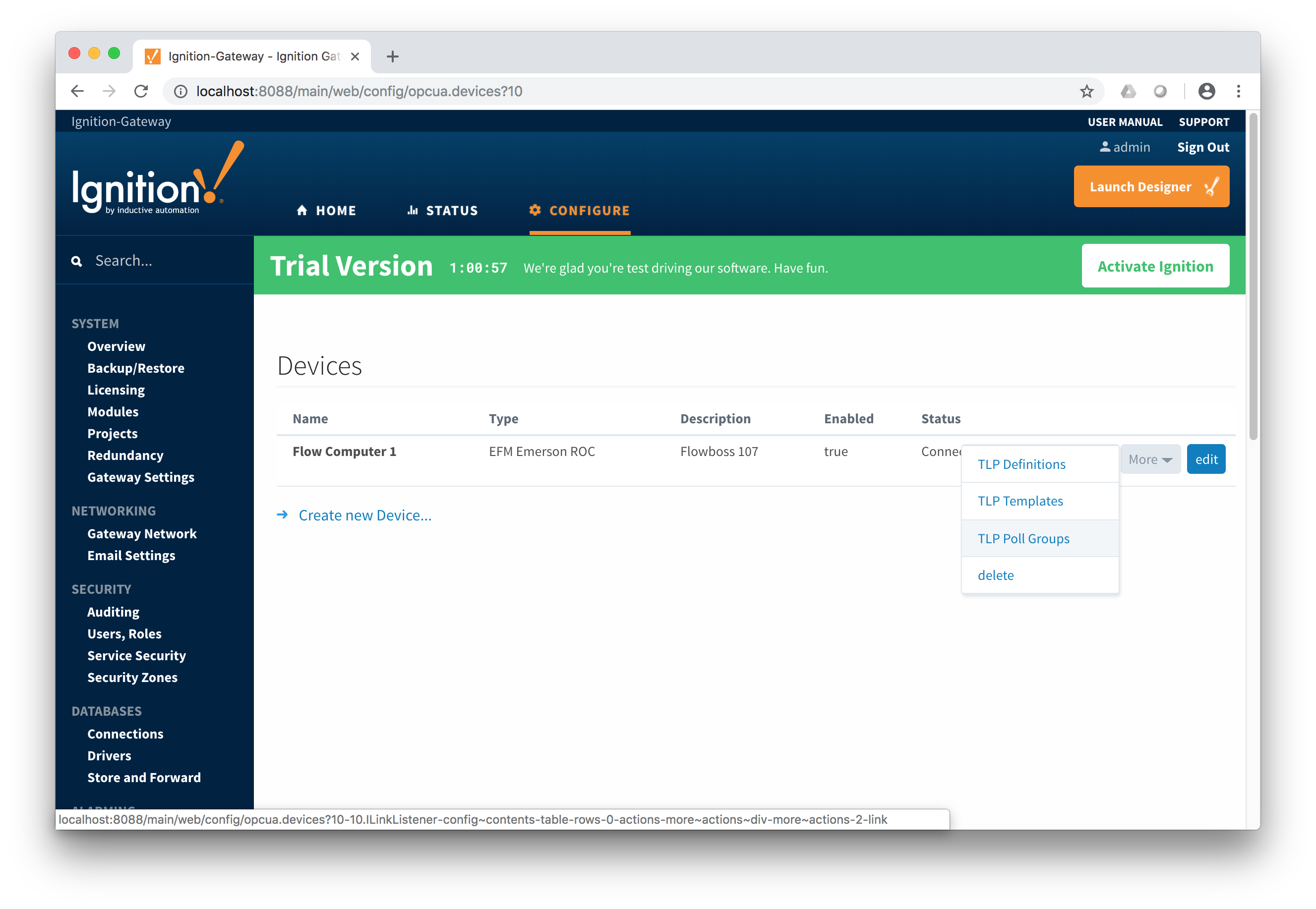
Creating TLP Poll Groups for a Device

With TLP templates already defined you can now create TLP poll groups which will poll a group of TLPs via a TLP template at a specific logical number at a specified rate.  Do so by selecting 'TLP Poll Groups' via the 'More' drop-down as shown below.

Image Removed

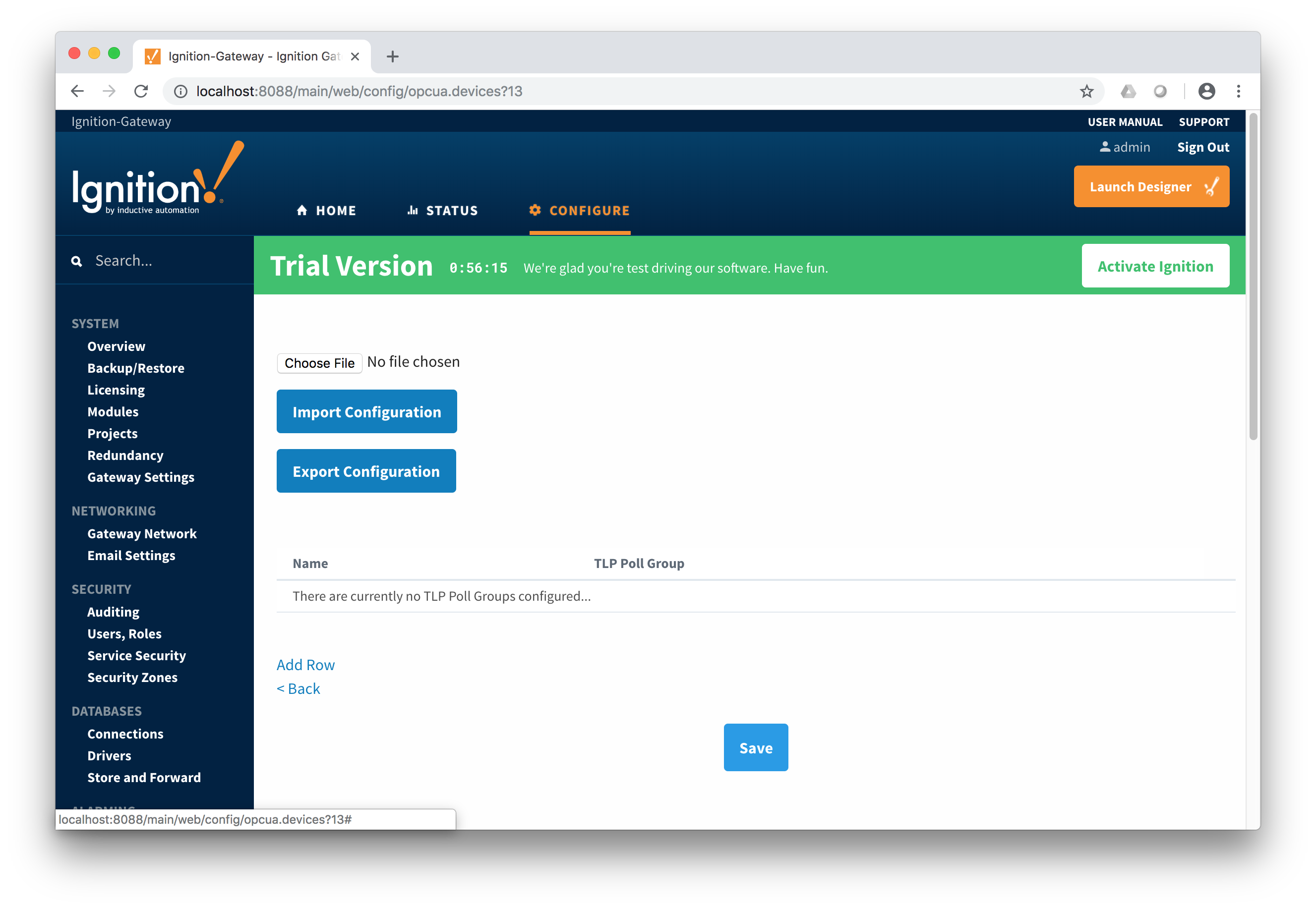
To add a TLP poll group, click the 'Add Row' link shown below.

Image Removed

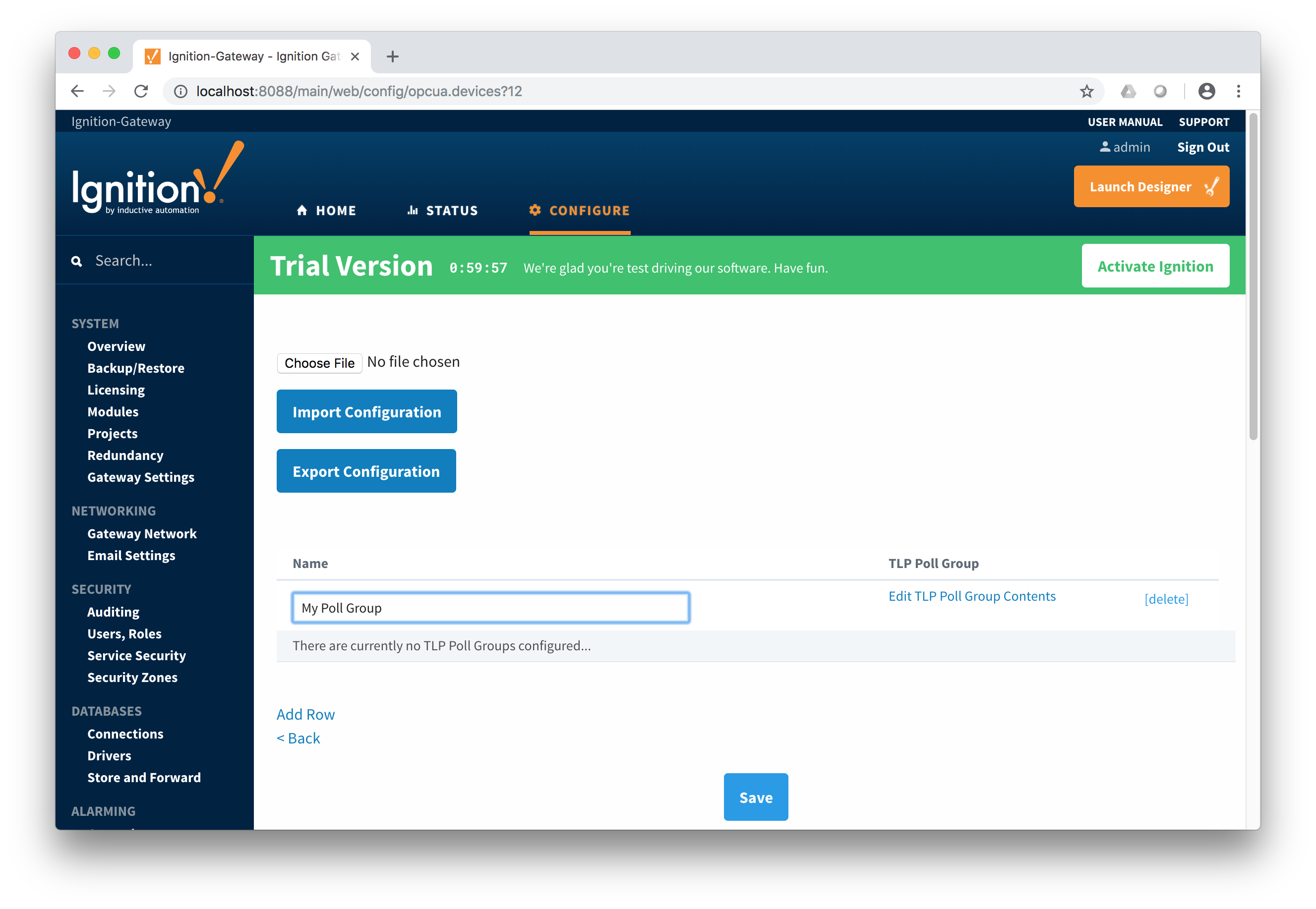
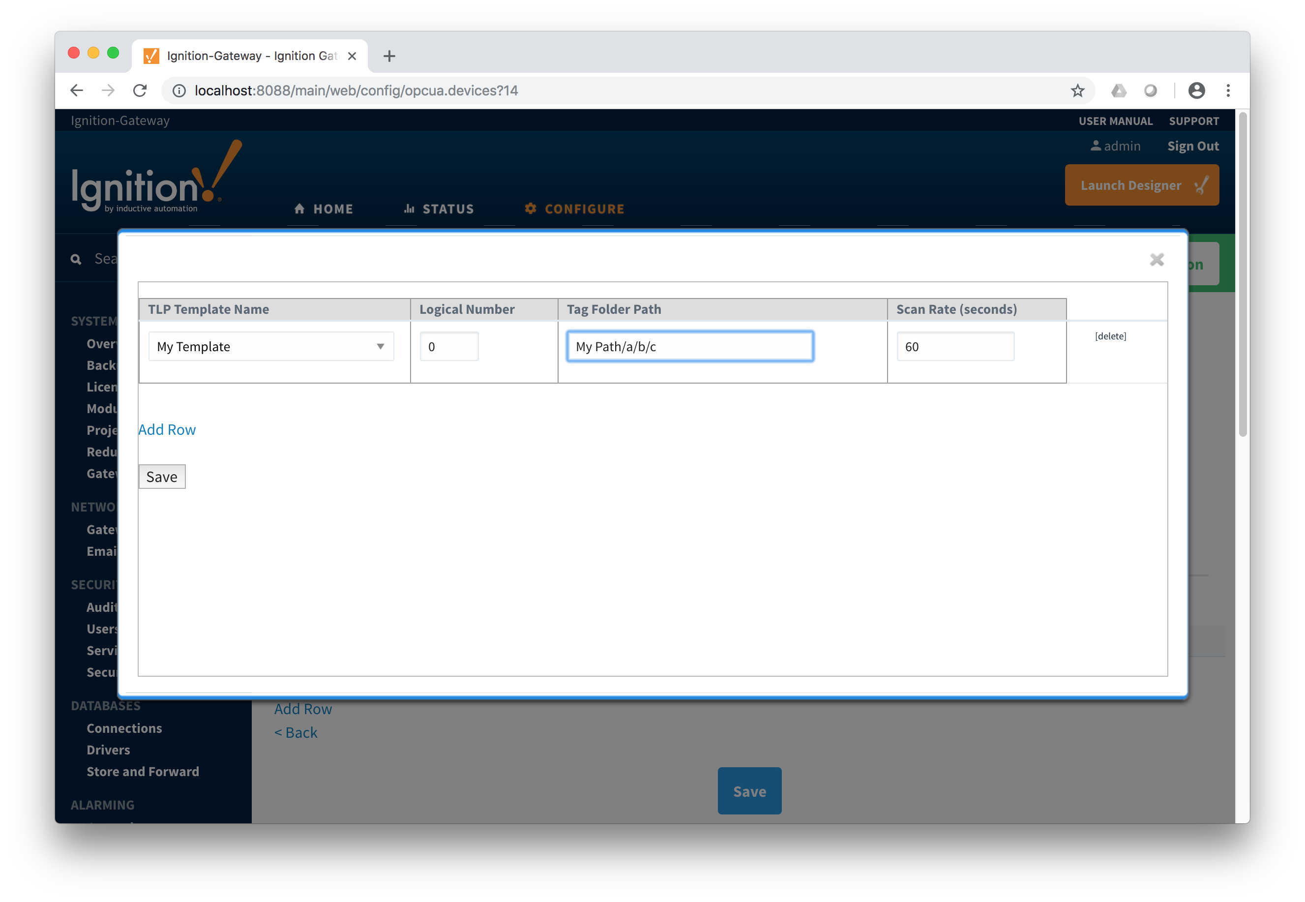
Now you can give the new TLP poll group a name that makes sense. Then click the 'Edit TLP Poll Group Contents' link next to the name field shown below.

Image Removed

At this point you can create a poll group using one or more TLP templates as shown below.  The parameters that must be set here are:

  • TLP Template Name
    • The TLP template to use for this poll group
    • The TLP templates available to choose from are based on the TLP templates defined for this device
  • Logical Number
    • The 'L' parameter of this TLP template.
  • Tag Folder Path
    • The tag folder path to use as the base for all TLP tags in this TLP template.
  • Scan Rate
    • The rate (in seconds) at which to poll all of the TLPs in this TLP template.

When complete, click the 'Save' button to save the TLP poll group.

Image RemovedCreate as many TLP poll groups as you'd like.  Once complete, click the 'Save' button at the bottom of the page below.

Image Removed

Viewing Device TLP Data

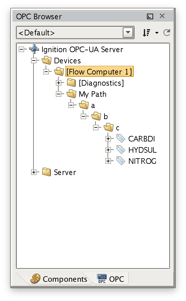
At this point the ROC device should be fully configured.  To view data in Ignition launch Ignition Designer and open the OPC Tag Browser as shown below.  You should see the tags being polled from the ROC device as shown below.  You can use these tags as any standard OPC tags in Ignition.

Image Removed

...

    • An ID representing a Device

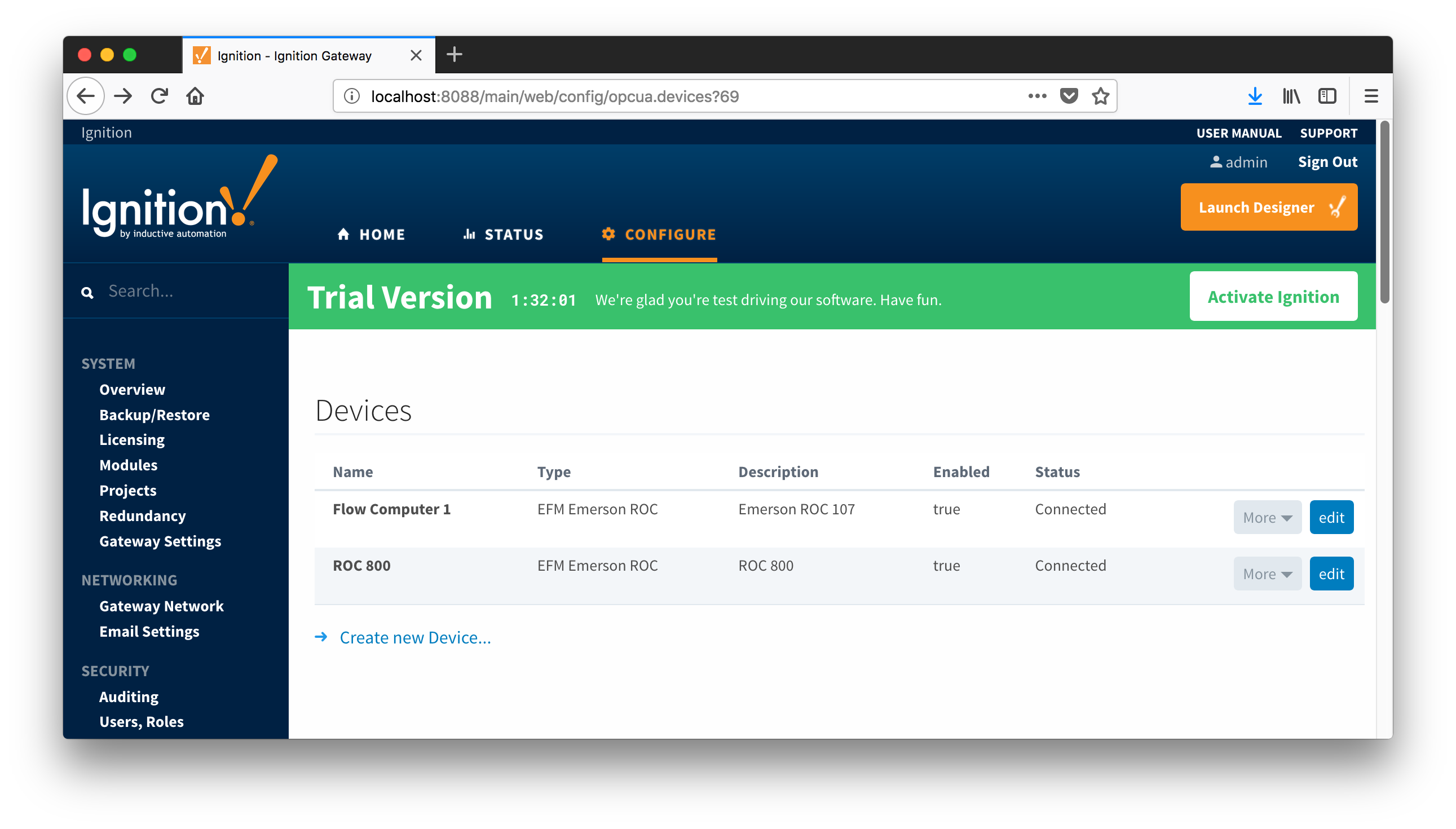
When all EFM Emerson ROC devices are configured, the Devices page will look as shown below:

Image Added

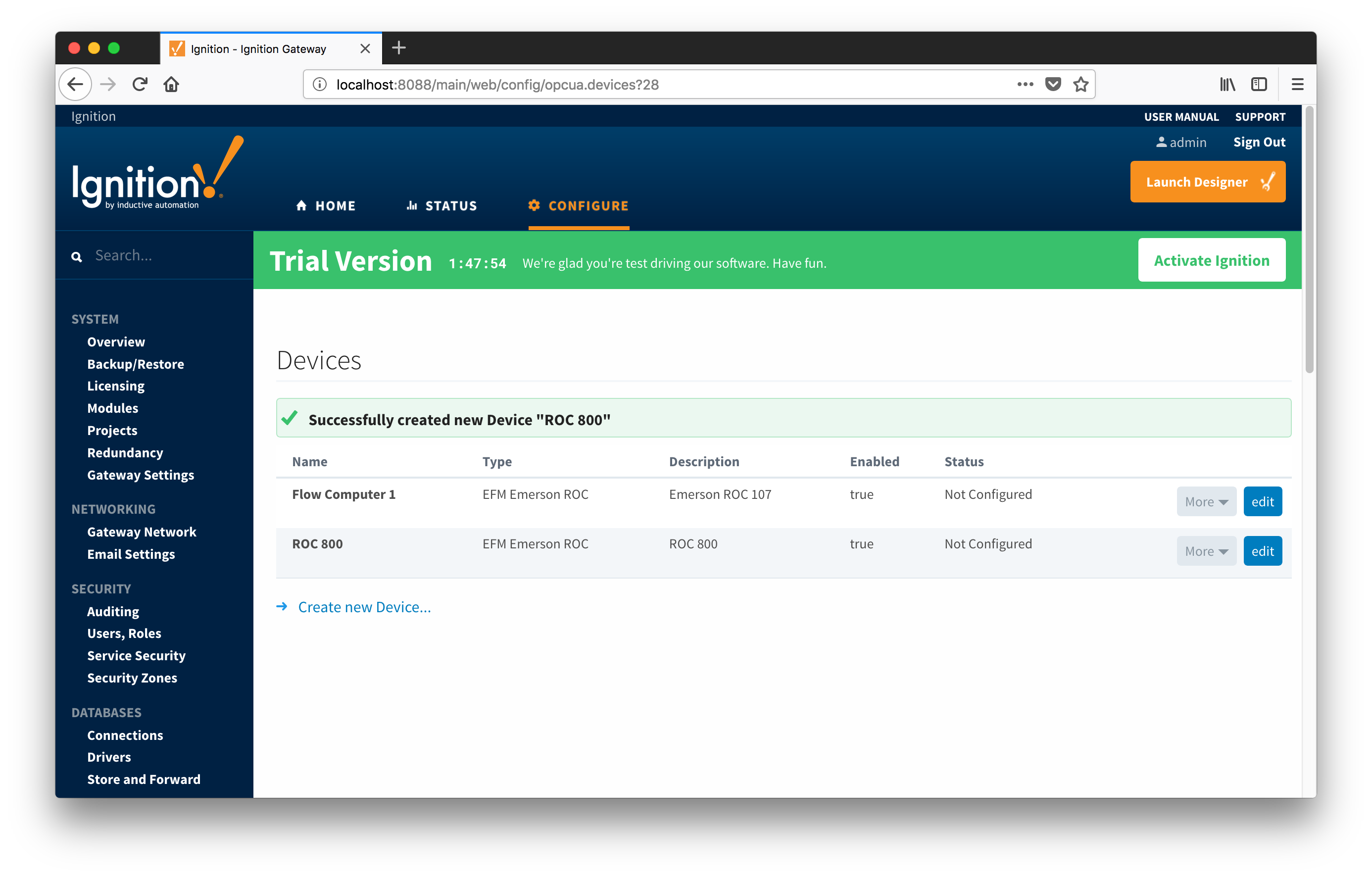
To finish configuring Emerson ROC and connect to physical devices, TLP definitions for each device need to be provided as described in the 'Specifying TLP Definitions for a Device' section of the EFM Emerson ROC Quickstart document. In short, the following three things need to be done:

  • Specify TLP Definitions 
  • Provide TLP Templates by importing TLP-template CSV file
  • Configure TLP Poll Groups by importing TLP-poll-group CSV file

When this is done, the 'Devices' configuration page will look as shown below with the 'Status' of each device set to 'Connected'.

Image Added