...
At this point, the Central Ignition Gateway with MQTT Distributor, MQTT Engine, and MQTT Recorder is fully configured and ready to receive MQTT Sparkplug messages from the Remote/Edge Ignition Gateway. MQTT Distributor listens on TCP port 1883 by default for inbound MQTT connections. Make sure the Operating System's Firewall, Antivirus, and Malware protection services allow inbound connections on port 1883/TCP before proceeding.
Remote/Edge Ignition Gateway Setup
With the Central Ignition Gateway ready to receive MQTT/Sparkplug RECORD objects, the EFM ABB Totalflow and MQTT Transmission modules can be configured on the Remote/Edge Ignition Gateway.
Start by configuring the MQTT Transmission module. Do so by opening Ignition Designer and creating a tag structure similar to what is shown below.
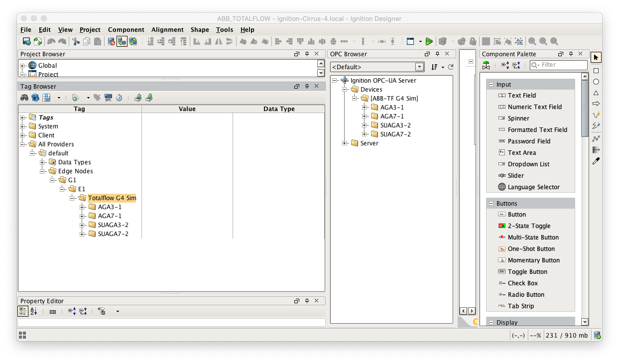 Image Modified
Note this structure is based on usage of the 'Default Transmitter' in MQTT Transmission. So, the directory structure is very important. Note the structure.
- tag provider/Edge Nodes/[Group ID]/[Edge Node ID]/[Device ID]/...
In the example below this implies the following definitions:
- [Group ID] = G1
- [Edge Node ID] = E1
- [Device ID] = Totalflow G4 Sim
These exact values will be used for the EFM ABB Totalflow connection Sparkplug parameters to tell the EFM ABB Totalflow which MQTT Transmission Transmitter configuration to use and, in turn, which MQTT connection to use to send the history data on.
Next the MQTT Transmission server configuration must be modified to point to the Central Ignition Gateway we set up earlier. To do so, in the Ignition Gateway Web UI browse to the Configure tab on the top and then to MQTT Transmission Settings in the lower left as shown below.
In the MQTT Transmission Settings configuration, click the Servers tab. Then click 'edit' on the Chariot SCADA MQTT Server definition. Modify the URL to match the URL of the Central Ignition Gateway. In this example, MQTT Distributor is installed on a Central Ignition Gateway at the IP address of 192.168.1.2. Once the URL is modified to match the configuration, there should be a '1 of 1' in the Connected column as shown below.
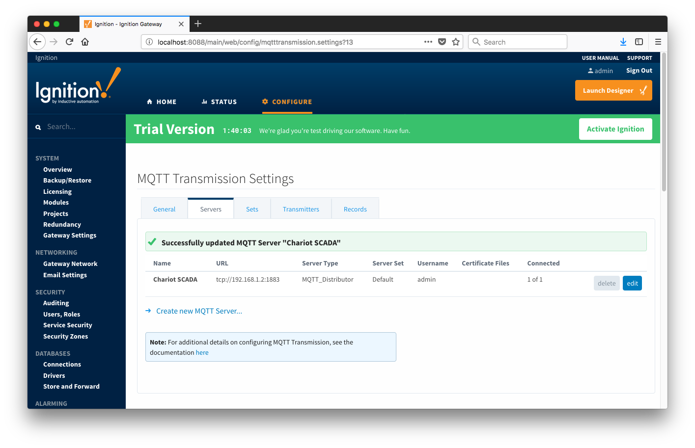 Image Modified
The next step is configuring the ABB Totalflow module. This is done as described in the ABB Totalflow Configuration manual. In going through the basic setup and configuration for Alarms configuration the following steps must be performed:
- Define the global Array-Registers definitions available for all ABB Totalflow devices in this Ignition instance
- This step can be skipped if not configuring the driver to poll for AAR data
- Upload the Periodic Mappings for all ABB Totalflow devices in this Ignition instance
- This step can be skipped if default mapping provided by the driver is ok.
- Create the base device connection to the ABB Totalflow device
- Specify the subset of global Array-Register definitions that this specific ABB Totalflow device uses
- This step can be skipped if not configuring the driver to poll for AAR data
- Reconfigure device connection to enable polling for Alarms
As en example, let's configure the driver to poll for Alarms and disable Events and History. First of all, alarms can come from two sources:
- Alarm flags in Periodic History Records (Array 250)
- Alarm Log Record (i.e. Array 245)
- The Alarm Log structure is returned from meters with the enhanced option turned on
If the 'Alarm Source' device configuration option is set to PERIODIC_HISTORY_RECORDS, the scan rates as shown below:
The first way is to set Periodic History scan rate as shown below:
- Alarm Scan Rate
- 0 Zero indicates that alarms are required
- Event Scan rate
- -1 Polling for Events is disabled
- Periodic History Scan Rate
- 0 Scan on notification form the 'Record Info' poller.
- Daily History Scan Rate
- -1 Polling for Daily History records is disabled
- Record Info Scan Rate
- Polling Totalflow registers for any changes of Alarms, Events, and History arrays and notification respective pollers is disabled.
The second way is to set Record Info scan rate and obtain alarms from Periodic History records on notifications from the 'Record Info' poller as shown below:
- Alarm Scan Rate
- 0 Zero indicates that alarms are required
- Event Scan rate
- -1 Polling for Events is disabled
- Periodic History Scan Rate
- 0 Scan on notification form the 'Record Info' poller.
- Daily History Scan Rate
- -1 Polling for Daily History records is disabled
- Record Info Scan Rate
- Needs to be set to a positive number to poll registers that contain information on Totalflow Record's Arrays (i.e. Alarms, Events, and History), and notify History Poller that there is a new entry in Array 250 (LOG_PERIOD_RECORD).
If the 'Alarm Source' device configuration option is set to Alarm Log Records (Array 245), the scan rates can be set in two ways:
This can be done in two ways:
At this point the EFM ABB Totalflow driver is configured and is polling for Alarms at the rate specified in the EFM ABB Totalflow device configuration.
MQTT Transmission is connected to the MQTT Server and as a result MQTT Engine is receiving tag change events. In addition, because an EFM ABB Totalflow device has been created and configured with the same Sparkplug Group ID, Edge Node ID, and Device ID, history data will also be pushed to the MQTT server as Sparkplug RECORD objects. When new history data is polled by the EFM ABB Totalflow driver, they will be published to the MQTT server, consumed by MQTT Engine, passed on to MQTT Recorder, and then inserted into the specified database. Below is a view of some events records using a third party database viewing tool.
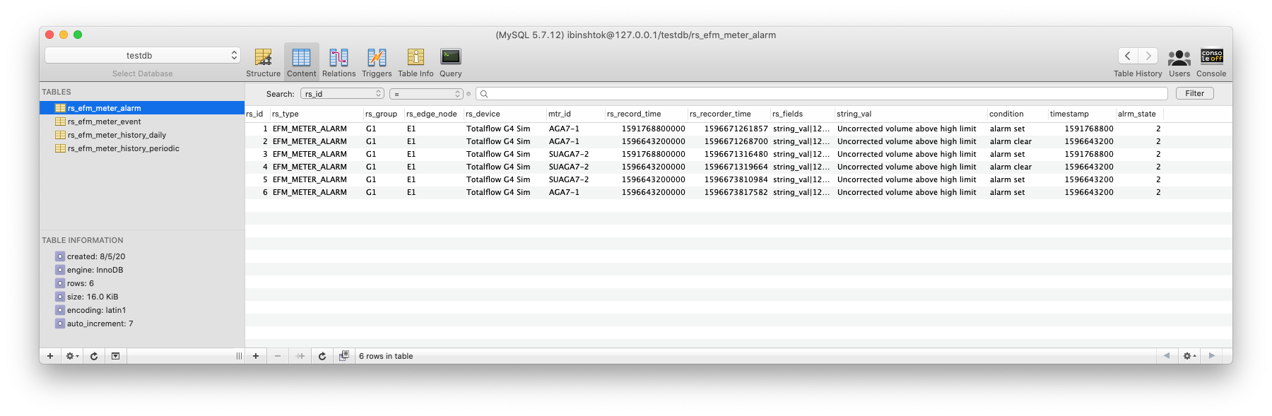 Image Modified