...
Once Ignition is installed, the MQTT Modules are installed, and everything is running we can configure the systems. Since we are going to have a backup for each master system, we only need to do most of the configuration for the master systems. Later, we can sync the configurations to the backups automatically. We'll start by configuring the modules and configure the redundancy settings in the next step.
Ignition Primary - MQTT Distributor
- No modifications to the default parameters are required. However, it is important to make sure the Operation System allows inbound connections on port 1883 and there are no firewalls blocking inbound connections on this port from the remote edge nodes.
Ignition Primary - MQTT Engine
- The only change from defaults is to set a Primary Host ID. MQTT uses Quality of Service (QOS) levels to ensure messages get delivered. However, this only ensures delivery between a single MQTT client and the MQTT server. In other words, it doesn't ensure delivery from one MQTT client to another MQTT client. Sparkplug introduces the notion of a Primary Host ID which is used to ensure client to client communications. The only requirement is that it match exactly on both the MQTT Engine and MQTT Transmission configurations.
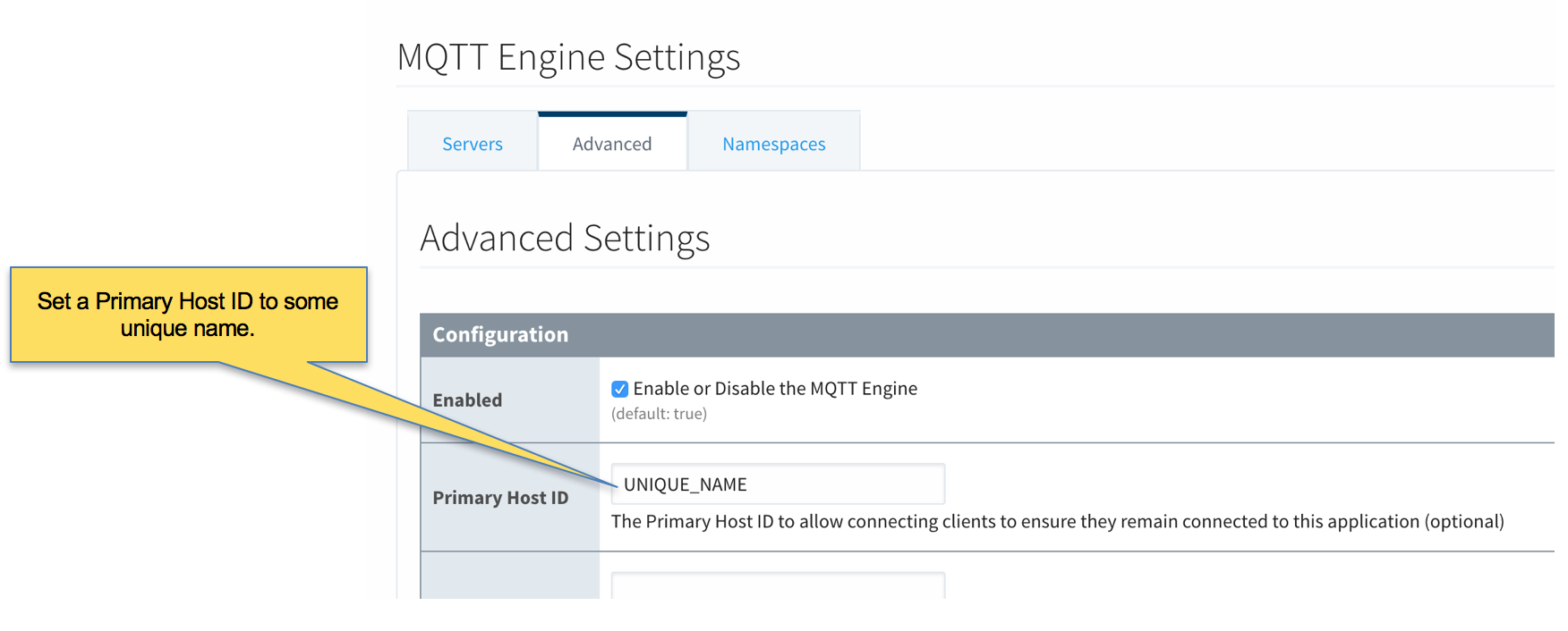 Image RemovedFor this tutorial the Primary Host ID will be "PRIMARY_HOST"
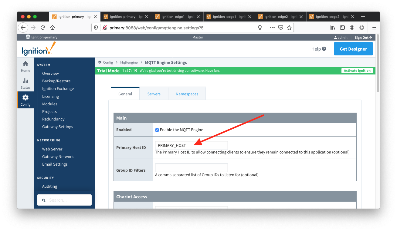 Image Added
Ignition Edge 1 and Ignition Edge 2 - MQTT Transmission (Configure the same on both Ignition instances)
- As with the MQTT Engine configuration, the Primary Host ID must be set configured on the General tab as shown below"Default" Set.
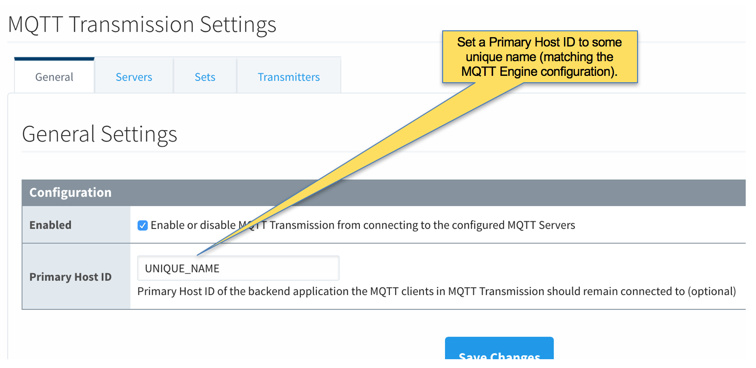 Image Removed
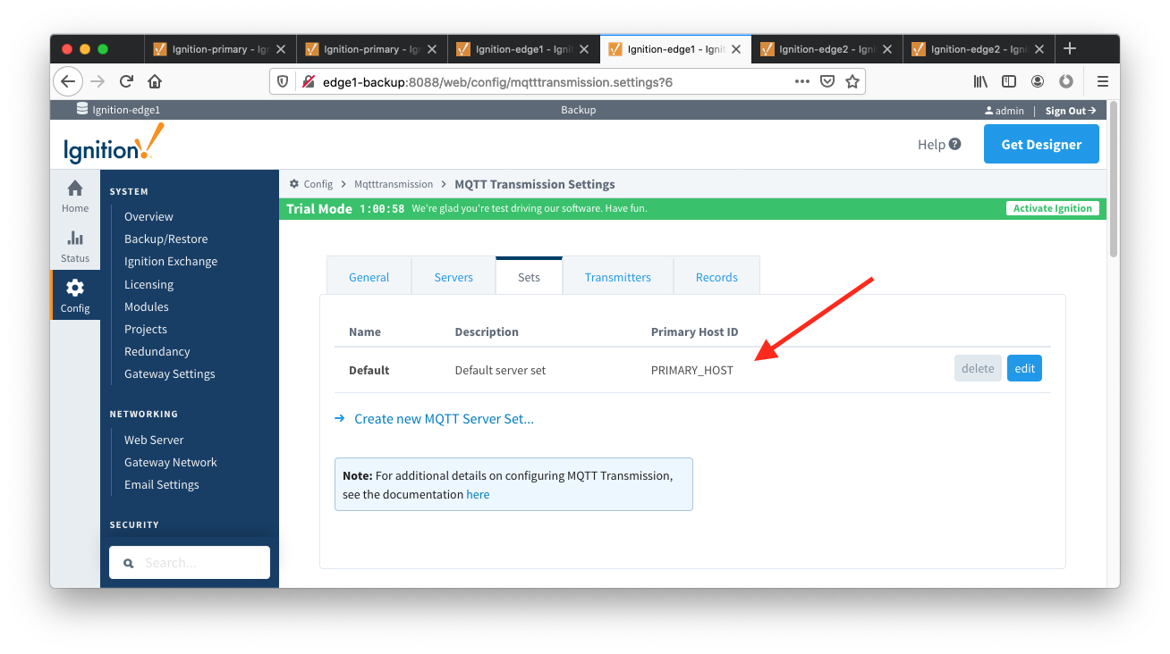 Image Added
- Delete the existing default MQTT Transmission Server"Chariot SCADA" Servers setting.
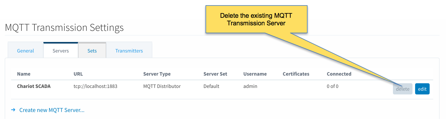 Image Removed
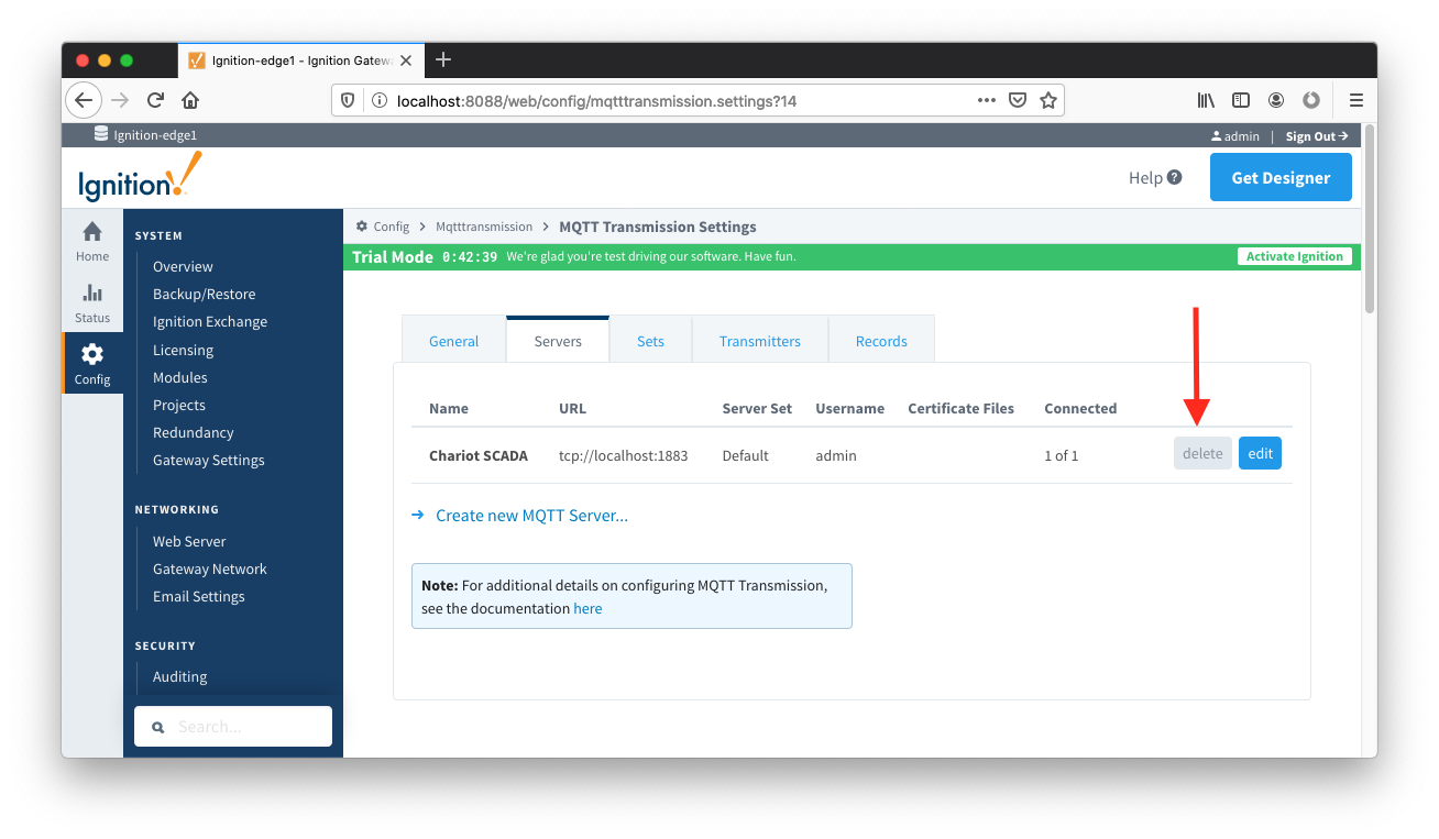 Image Added
- Create a new MQTT Server configuration by clicking the link below.
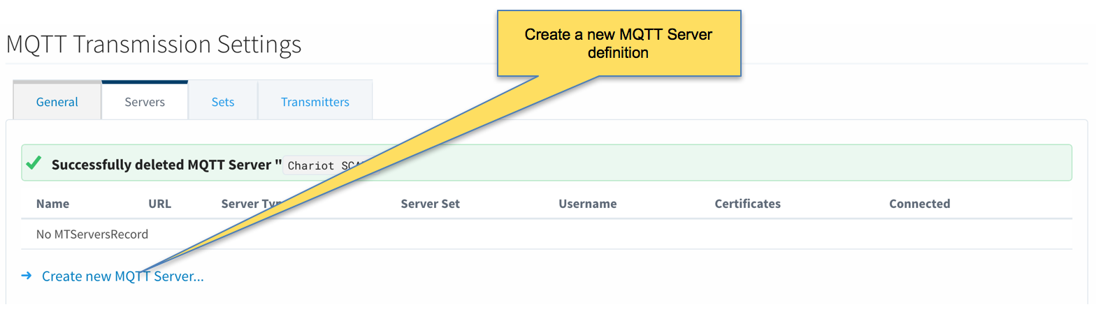 Image Removed
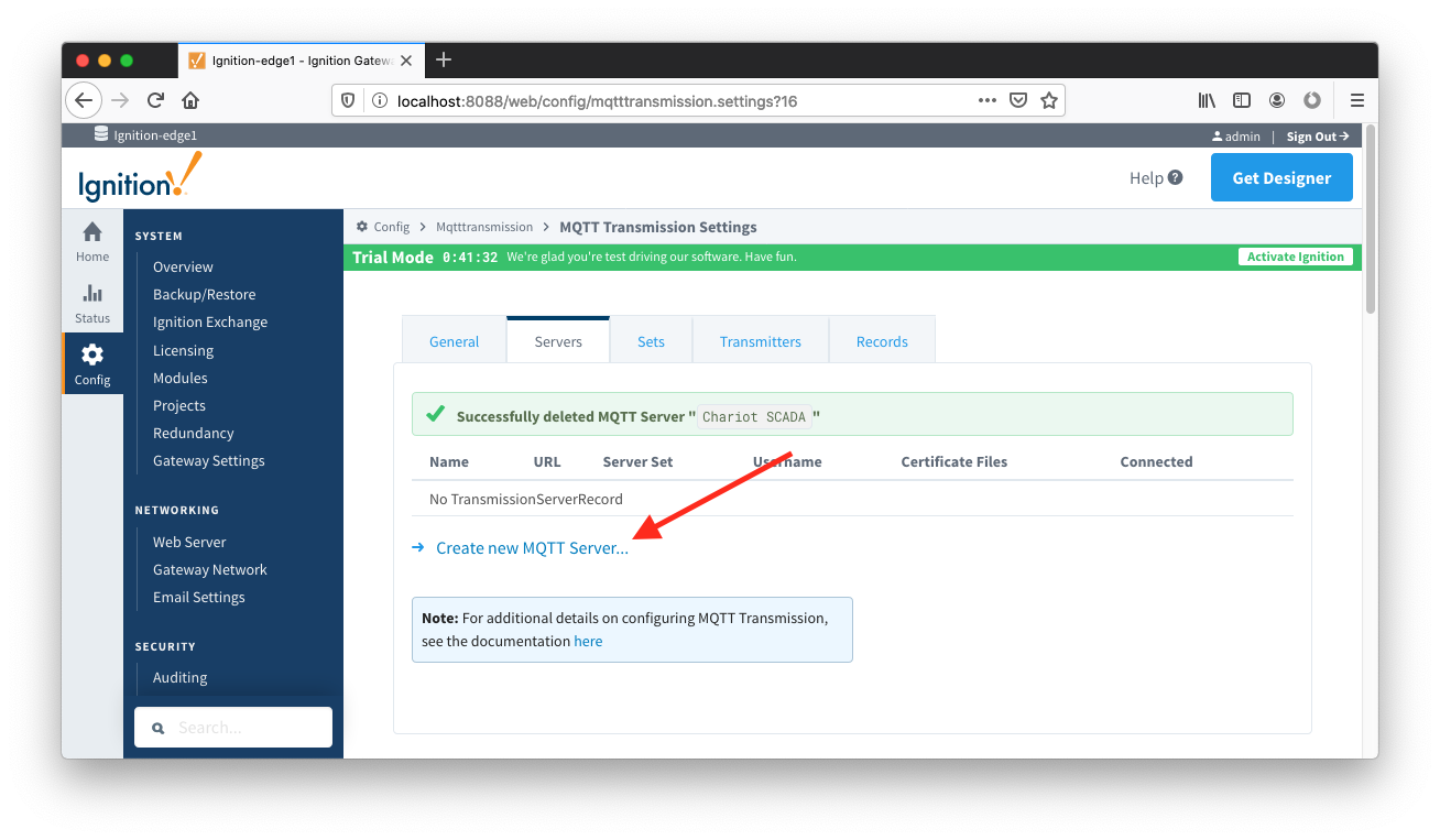 Image Added
- Configure MQTT Transmission to point to the Primary Ignition. Configure as shown below making sure to change the URL to reflect your network settings. For example, if you Ignition Primary is at 192.168.1.100 the MQTT Server URL would be: tcp://192.168.1.100:1883. After setting the parameters as shown below. Click the 'Save Changes' button at the bottom.
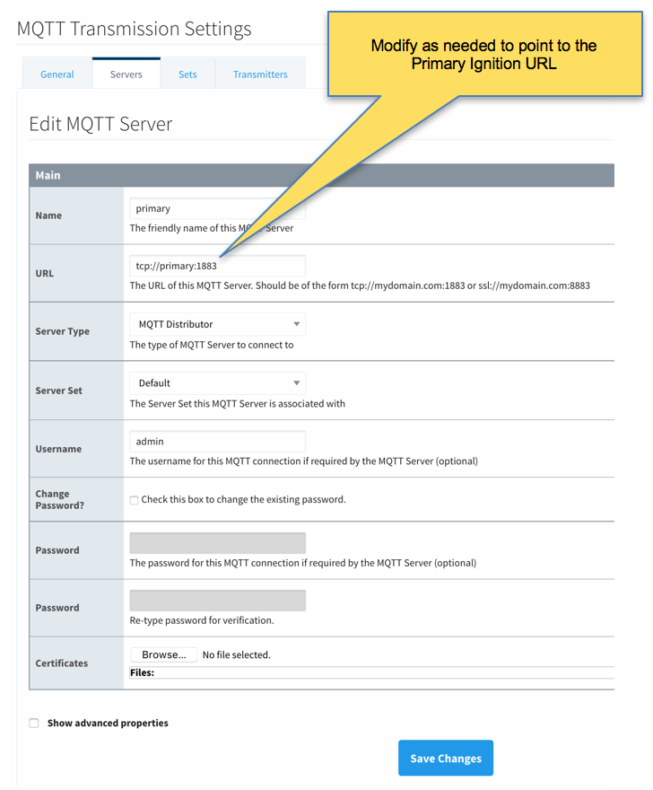 Image RemovedVerify the MQTT Server has been created and is shown in the list of MQTT Servers as shown below.
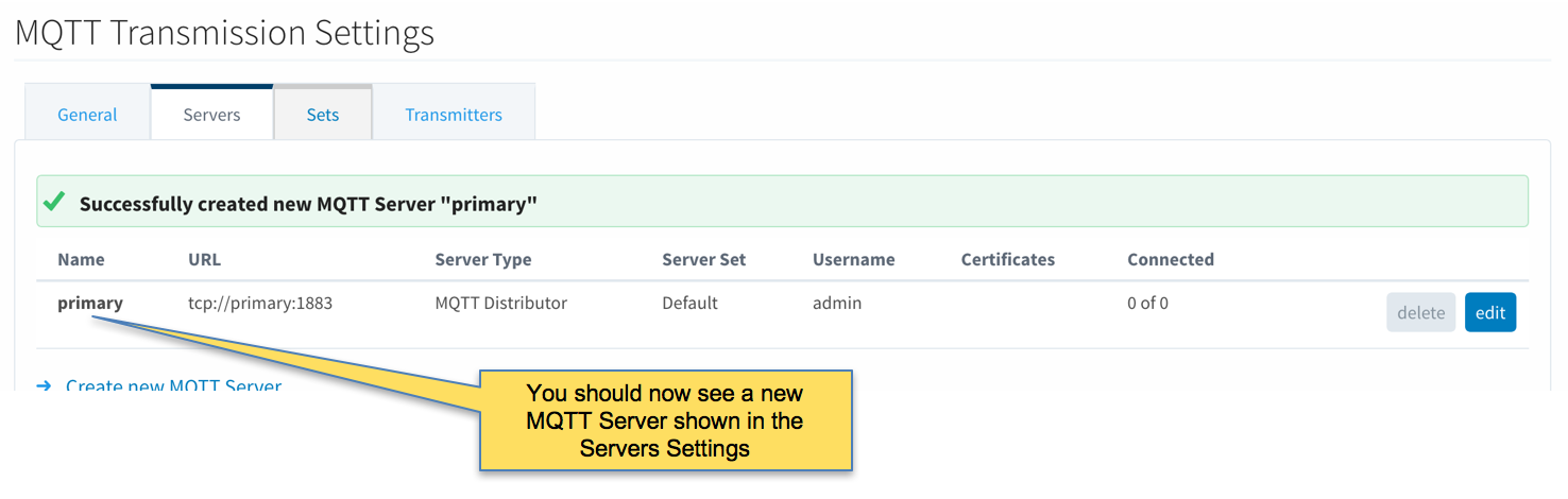 Image Removed
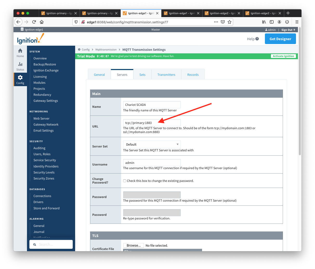 Image Added
- Repeat the process of creating a MQTT Server but instead point it to the Ignition Primary Backup MQTT Server. These are the parameters to use:
- Name: primary-backup
- URL: tcp://primary-backup:1883
- Change 'primary-backup' in the URL to reflect the network address of the Ignition Primary Backup server.
- Server Type: MQTT Distributor
- Server Set: Default
- Username: admin
- Password: changeme
- When complete, verify both MQTT Servers appear in the list as shown below.
 Image Removed
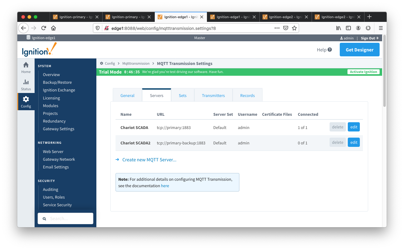 Image Added
- Finally, make sure to set up the same MQTT Transmission configuration in the Ignition Edge 2 instance.
Step 4: Configure Redundancy
...
https://docs.inductiveautomation.com/display/DOC/Setting+Up+Redundancy
https://support.inductiveautomation.com/usermanuals/ignition/index.html?redundancy_settings.htm
Ignition Primary
- Select Redundancy on the left navigation bar. Then set the Mode to 'Master' and set the Standby Activity left to 'Warm' as shown below.
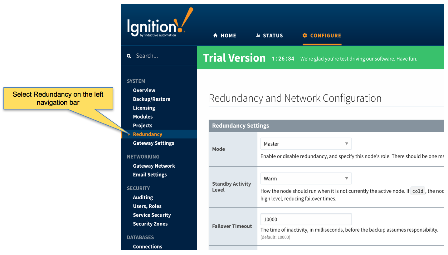 Image Removed
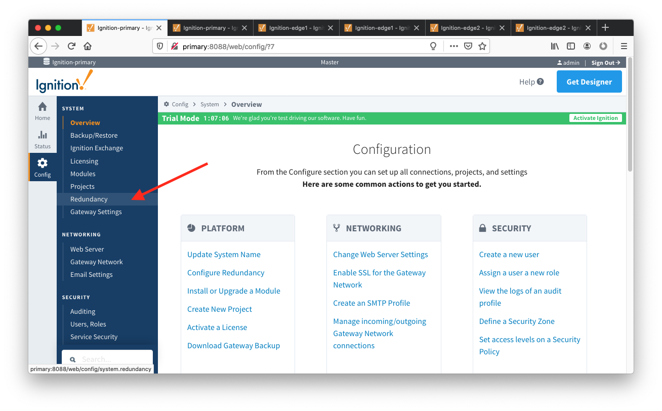 Image Added
- Set up the Redundancy Network Settings. The settings here are specific to your network setup. On many LAN configurations none of these changes are required. What is shown below was the configuration for setting up all of these components in Amazon's AWS EC2 instances. The changes were:
- Uncheck 'Auto-detect network interface'
- Set the 'Network Bind Interface' to the public IP address of the Ignition Primary EC2 instance. On a LAN this would be the primary network interface address of the Ignition Primary machine.
- Uncheck the 'Autodetect HTTP Address' tickbox.
Specify two explicit HTTP addresses for clients to use. These were the public IP addresses of the Ignition Primary and Ignition Primary Backup EC2 instances. On a LAN, these would
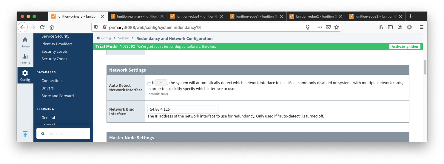 Image Added
- Set the Master Node Address. Note in the configuration below a hostname is being used. This should be the primary network interface addresses address of the Ignition Primary and Ignition Primary Backup machines. Also note the HTTP port is 8088 which is the default Ignition HTTP port.
 Image RemovedGateway.
 Image Added
- Set the Master Node Address. Note in the configuration below a hostname is being used. This should be the primary network interface address of the Ignition Primary Gateway.
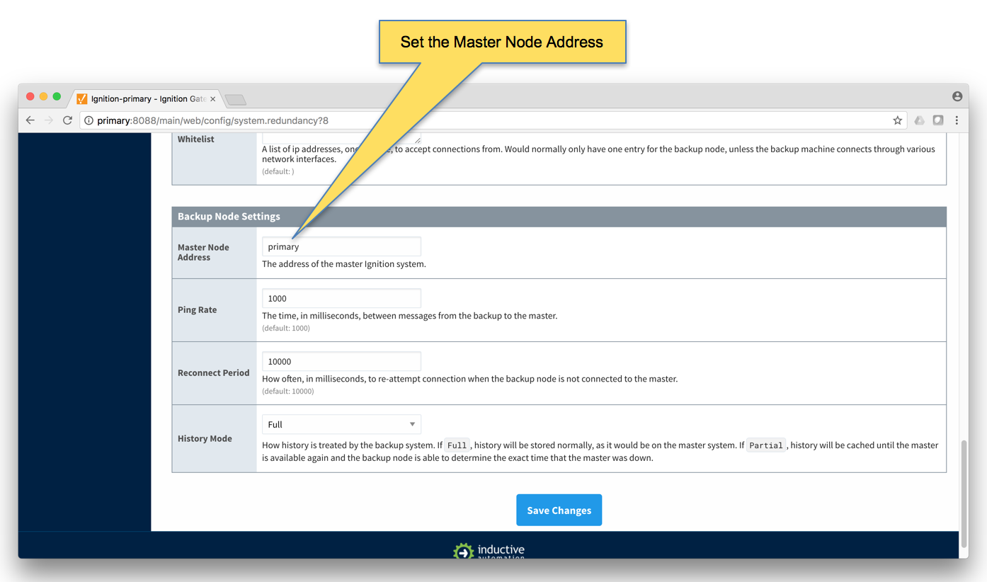 Image Removed
 Finally, click the 'Save Changes' button.
Ignition Primary Backup
- Select Redundancy on the left navigation bar. Then set the Mode to 'Backup' and set the Standby Activity left to 'Warm' as shown below.
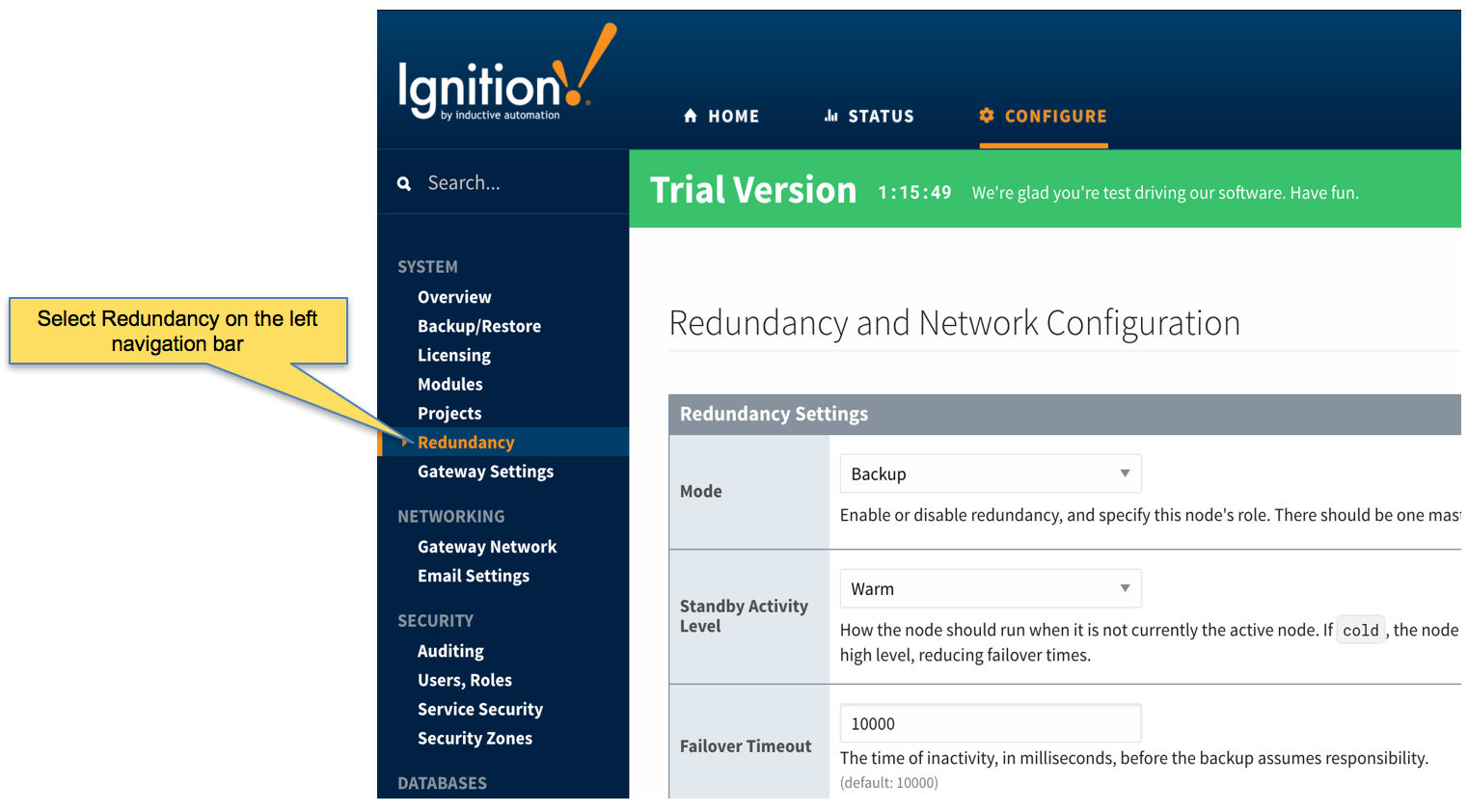 Image Removed
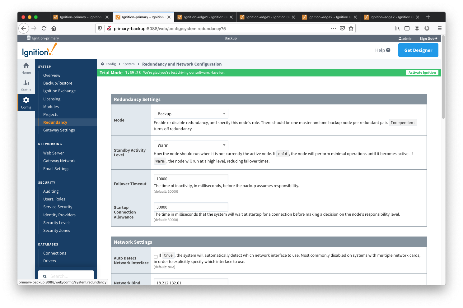 Image Added
- Set up the Redundancy Network Settings. The settings here are specific to your network setup. On many LAN configurations none of these changes are required. What is shown below was the configuration for setting up all of these components in Amazon's AWS EC2 instances. The changes were:
- Uncheck 'Auto-detect network interface'
- Set the 'Network Bind Interface' to the public IP address of the Ignition Primary Backup EC2 instance. On a LAN this would be the primary network interface address of the Ignition Primary Backup machine.
- Uncheck the 'Autodetect HTTP Address' tickbox.
- Specify two explicit HTTP addresses for clients to use. These were the public IP addresses of the Ignition Primary and Ignition Primary Backup EC2 instances. On a LAN, these would be the primary network interface addresses of the Ignition Primary and Ignition Primary Backup machines. Also note the HTTP port is 8088 which is the default Ignition HTTP port.
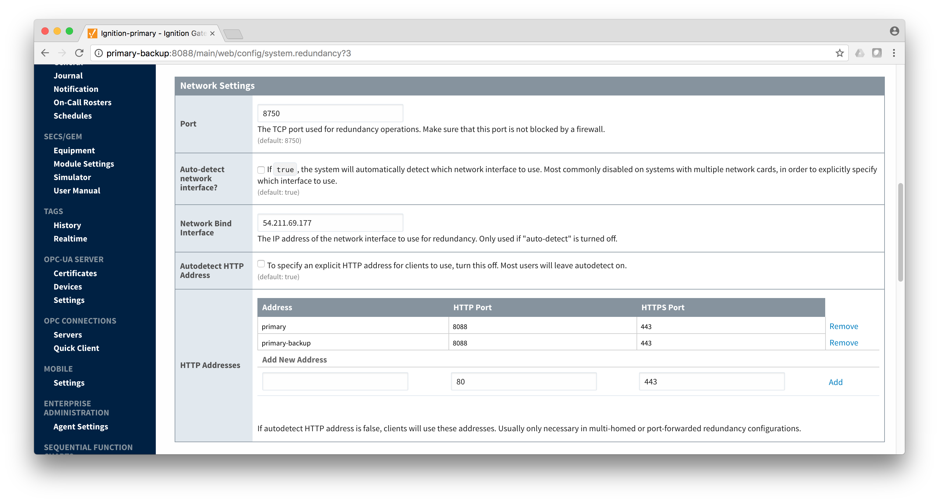 Image Removed
 Set the Master Node Address. Note in the
Set the Master Node Address. Note in the configuration below a hostname is being used. This should be the primary network interface address of the Ignition Primary Gateway.Image Removed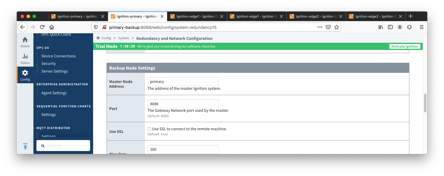 Image Added
- Finally, click the 'Save Changes' button.
Ignition Edge 1
- Select Redundancy on the left navigation bar. Then set the Mode to 'Master' and set the Standby Activity left to 'Warm' as shown below.Image Removed
 Image Added
- Set up the Redundancy Network Settings. The settings here are specific to your network setup. On many LAN configurations none of these changes are required. What is shown below was the configuration for setting up all of these components in Amazon's AWS EC2 instances. The changes were:
- Uncheck 'Auto-detect network interface'
- Set the 'Network Bind Interface' to the public IP address of the Ignition Edge 1 EC2 instance. On a LAN this would be the primary network interface address of the Ignition Edge 1 machine.
- Uncheck the 'Autodetect HTTP Address' tickbox.
network interface'
- Set the 'Network Bind Interface' to the public IP address Specify two explicit HTTP addresses for clients to use. These were the public IP addresses of the Ignition Edge 1 and Ignition Edge 1 Backup EC2 instancesinstance. On a LAN , these this would be the primary network interface addresses of the Ignition Edge 1 and Ignition Edge 1 Backup machines. Also note the HTTP port is 8088 which is the default Ignition HTTP port.
 Image Removedaddress of the Ignition Edge 1 machine.
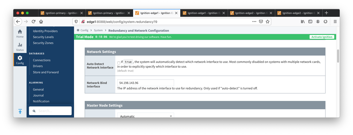 Image Added
- Set the Master Node Address. Note in the configuration below a hostname is being used. This should be the primary network interface address of the Ignition Edge 1 Gateway.
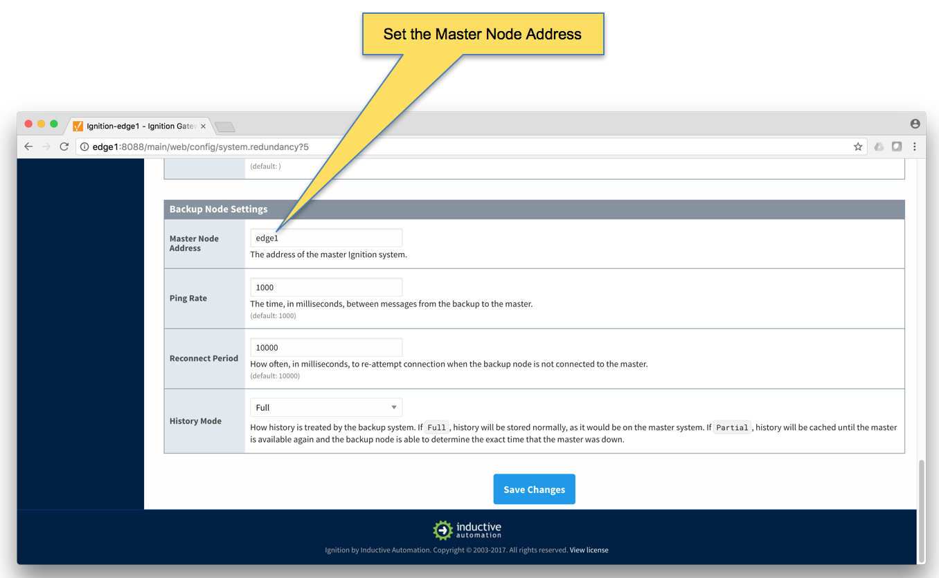 Image Removed
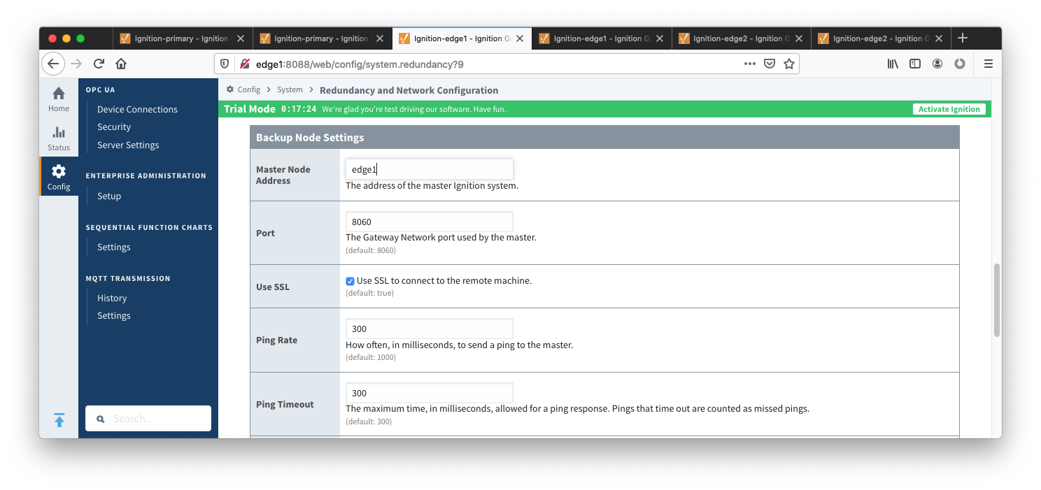 Image Added
- Finally, click the 'Save Changes' button.
Ignition Edge 1 Backup
- Select Redundancy on the left navigation bar. Then set the Mode to 'Backup' and set the Standby Activity left to 'Warm' as shown below.
 Image Removed
 Image Added
- Set up the Redundancy Network Settings. The settings here are specific to your network setup. On many LAN configurations none of these changes are required. What is shown below was the configuration for setting up all of these components in Amazon's AWS EC2 instances. The changes were:
- Uncheck 'Auto-detect network interface'
- Set the 'Network Bind Interface' to the public IP address of the Ignition Edge 1 Backup EC2 instance. On a LAN this would be the primary network interface address of the Ignition Edge 1 Backup machine.
- Uncheck the 'Autodetect HTTP Address' tickbox.
Specify two explicit HTTP addresses for clients to use. These were the public IP addresses of the Ignition Edge 1 and Ignition Edge 1 Backup EC2 instancesinstance. On a LAN , these this would be the primary network interface addresses address of the Ignition Edge 1 and Ignition Edge 1 Backup machines. Also note the HTTP port is 8088 which is the default Ignition HTTP port. Image Removedmachine.
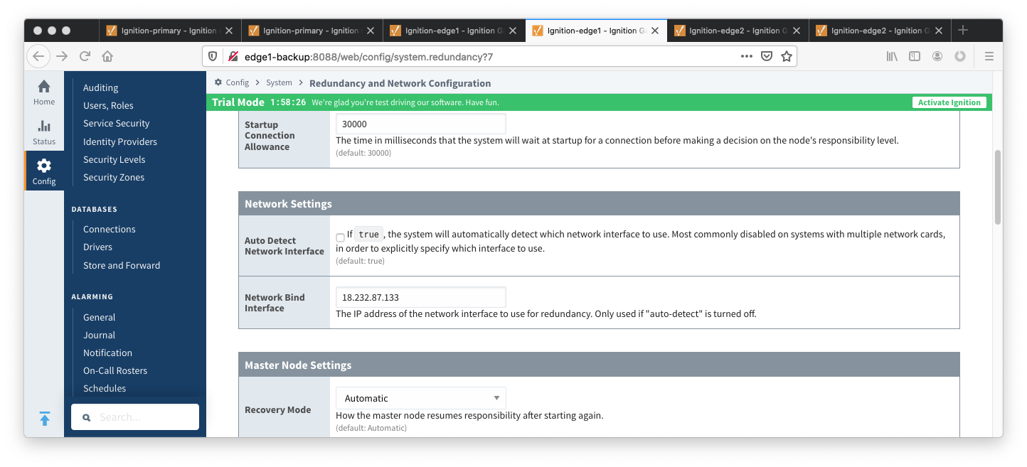 Image Added
- Set the Master Node Address. Note in the configuration below a hostname is being used. This should be the primary network interface address of the Ignition Edge 1 Gateway.
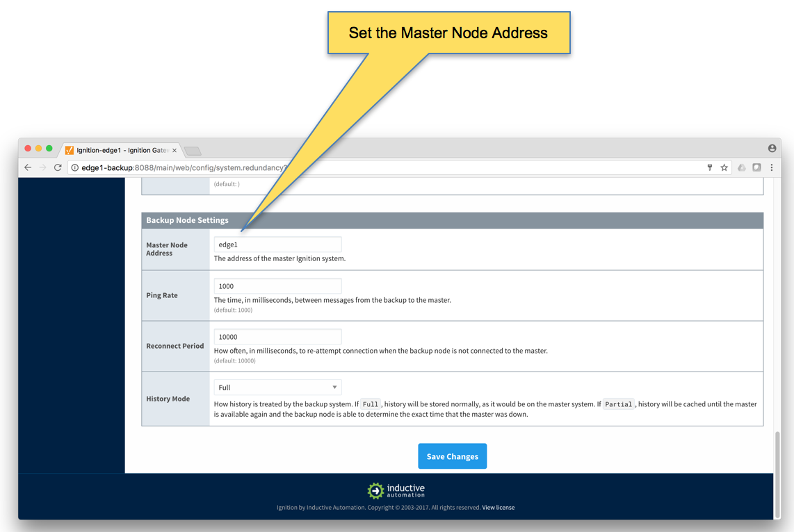 Image Removed
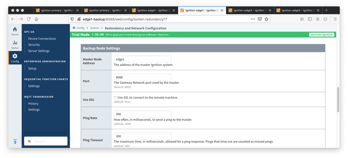 Image Added
- Finally, click the 'Save Changes' button.
Ignition Edge 2
- Select Redundancy on the left navigation bar. Then set the Mode to 'Master' and set the Standby Activity left to 'Warm' as shown below.Image Removed
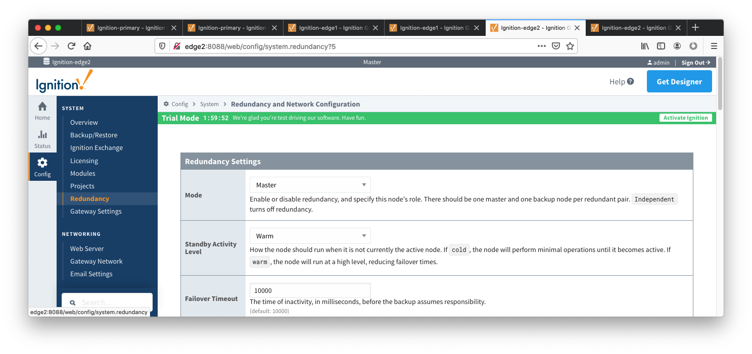 Image Added
- Set up the Redundancy Network Settings. The settings here are specific to your network setup. On many LAN configurations none of these changes are required. What is shown below was the configuration for setting up all of these components in Amazon's AWS EC2 instances. The changes were:
- Uncheck 'Auto-detect network interface'detect network interface'
- Set the 'Network Bind Interface' to the public IP address
- Set the 'Network Bind Interface' to the public IP address of the Ignition Edge 2 EC2 instance. On a LAN this would be the primary network interface address of the Ignition Edge 2 machine.
- Uncheck the 'Autodetect HTTP Address' tickbox.
Specify two explicit HTTP addresses for clients to use. These were the public IP addresses of the Ignition Edge 2 and Ignition Edge 2 Backup EC2 instancesinstance. On a LAN , these this would be the primary network interface addresses of the Ignition Edge 2 and Ignition Edge 2 Backup machines. Also note the HTTP port is 8088 which is the default Ignition HTTP port.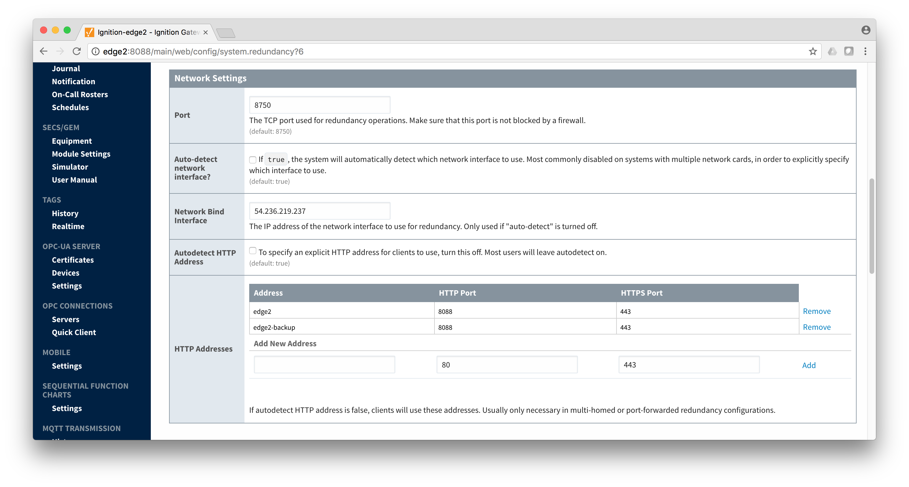 Image Removedaddress of the Ignition Edge 2 machine.
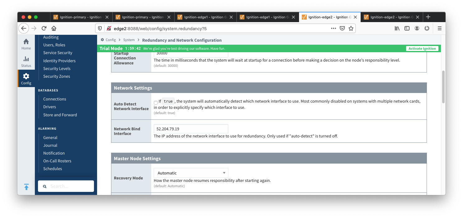 Image Added
- Set the Master Node Address. Note in the configuration below a hostname is being used. This should be the primary network interface address of the Ignition Edge 2 Gateway.
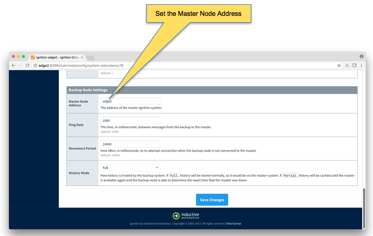 Image Removed
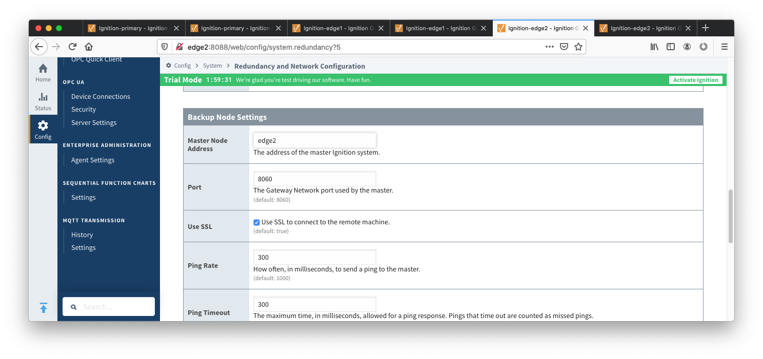 Image Added
- Finally, click the 'Save Changes' button.
Ignition Edge 2 Backup
- Select Redundancy on the left navigation bar. Then set the Mode to 'Backup' and set the Standby Activity left to 'Warm' as shown below.
 Image Removed
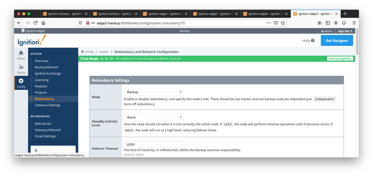 Image Added
- Set up the Redundancy Network Settings. The settings here are specific to your network setup. On many LAN configurations none of these changes are required. What is shown below was the configuration for setting up all of these components in Amazon's AWS EC2 instances. The changes were:
- Uncheck 'Auto-detect network interface'
- Set the 'Network Bind Interface' to the public IP address of the Ignition Edge 2 Backup EC2 instance. On a LAN this would be the primary network interface address of the Ignition Edge 2 Backup machine.
- Uncheck the 'Autodetect HTTP Address' tickbox.
Specify two explicit HTTP addresses for clients to use. These were ' to the public IP addresses address of the Ignition Edge Ignition Edge 2 and Ignition Edge 2 Backup EC2 instancesinstance. On a LAN , these this would be the primary network interface addresses address of the Ignition Edge 2 and Ignition Edge 2 Backup machines. Also note the HTTP port is 8088 which is the default Ignition HTTP port. Image Removedmachine.
 Image Added
- Set the Master Node Address. Note in the configuration below a hostname is being used. This should be the primary network interface address of the Ignition Edge 2 Gateway.
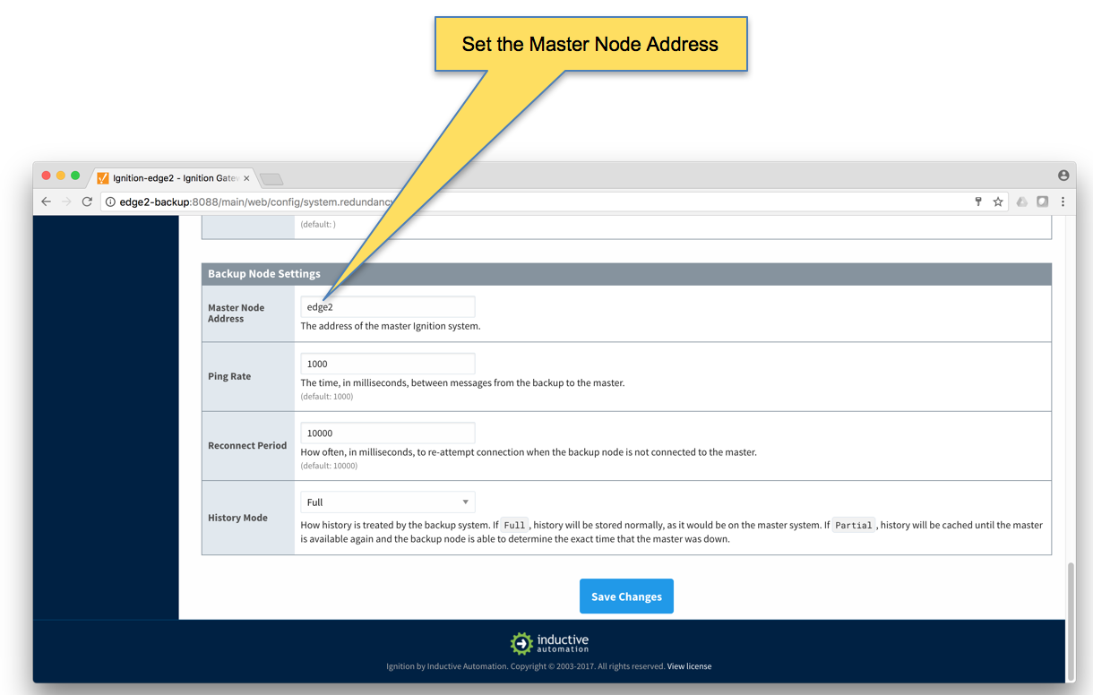 Image Removed
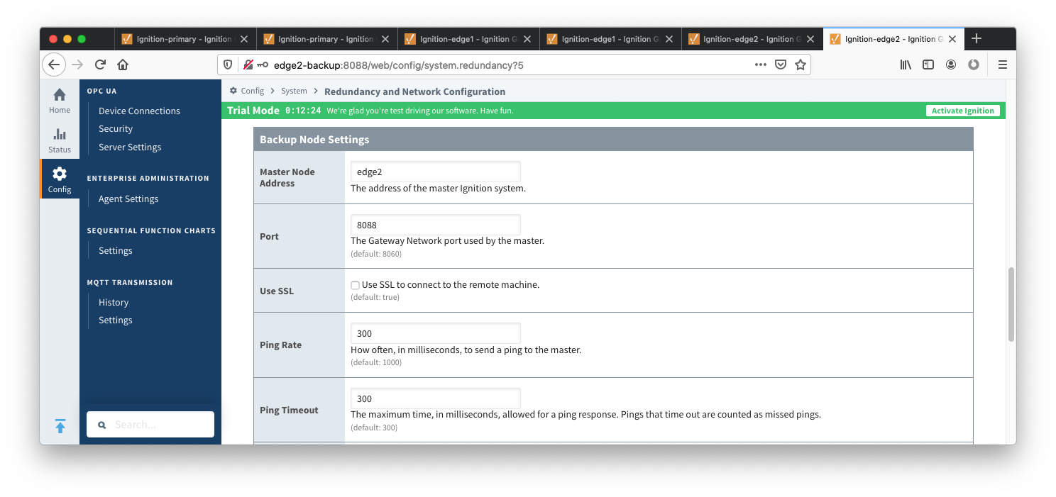 Image Added
- Finally, click the 'Save Changes' button.
Step 5: Create some tags in Edge 1 and Edge 2
...
- Using Ignition Designer on Edge 1, do the following:
- Create a new project called 'Test'.
- In the Tag Browser, confirm there is a folder called 'Edge Nodes'. If there is not, confirm MQTT Transmission is installed.
- In the 'Edge Nodes' folder, create a folder called 'Group 1'.
- In the 'Group 1' folder, create a folder called 'Edge 1'.
- In the 'Edge 1' folder, create a folder called 'Device 1'.
- In the 'Device 1' folder, create a Tag called 'Tag 1'.
- At the end, you should see something similar to what is shown below.
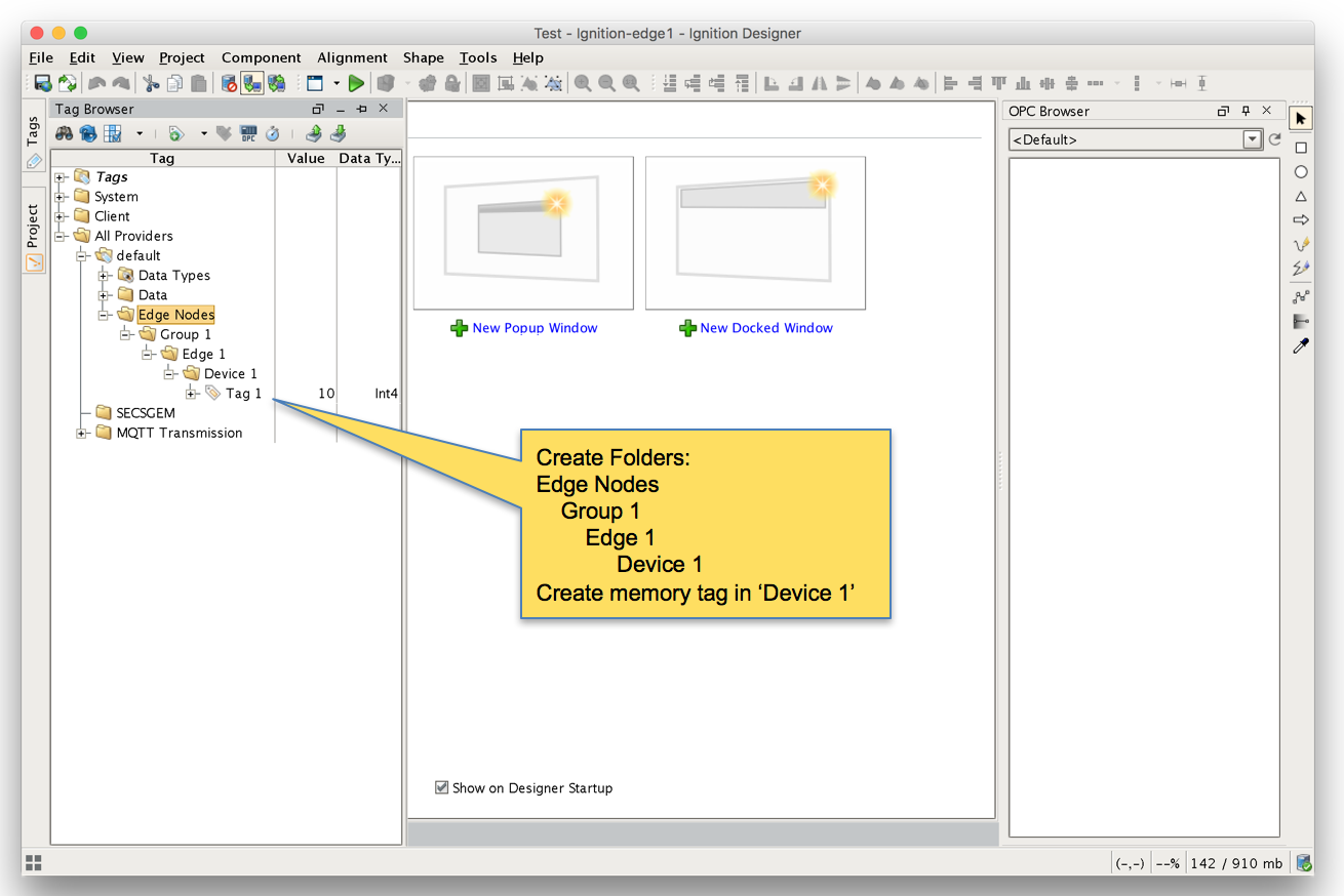 Image Removed
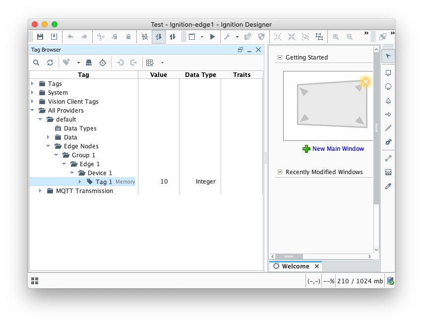 Image Added
- Using Ignition Designer on Edge 2, do the following:
- Create a new project called 'Test'.
- In the Tag Browser, confirm there is a folder called 'Edge Nodes'. If there is not, confirm MQTT Transmission is installed.
- In the 'Edge Nodes' folder, create a folder called 'Group 1'.
- In the 'Group 1' folder, create a folder called 'Edge 2'.
- In the 'Edge 2' folder, create a folder called 'Device 1'.
- In the 'Device 1' folder, create a Tag called 'Tag 1'.
- At the end, you should see something similar to what is shown below
...
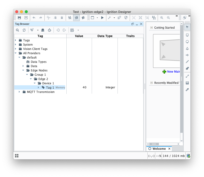 Image Added
- Finally, refresh the Transmission runtime. This is done by clicking the 'MQTT Transmission/Transmission Control/Refresh' Boolean tag.
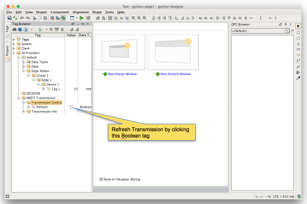 Image Removed
 Image Added
- After clicking the Boolean tag you may need to 'Enable
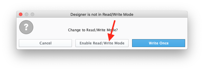 Image Added
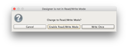 Image RemovedStep 6: Force Sync of Backup Instances
...
- Repeat the following steps for the following Ignition instances: Primary, Edge 1, and Edge 2
- Browse to the Status menu and then click in the Redundancy box as shown below.
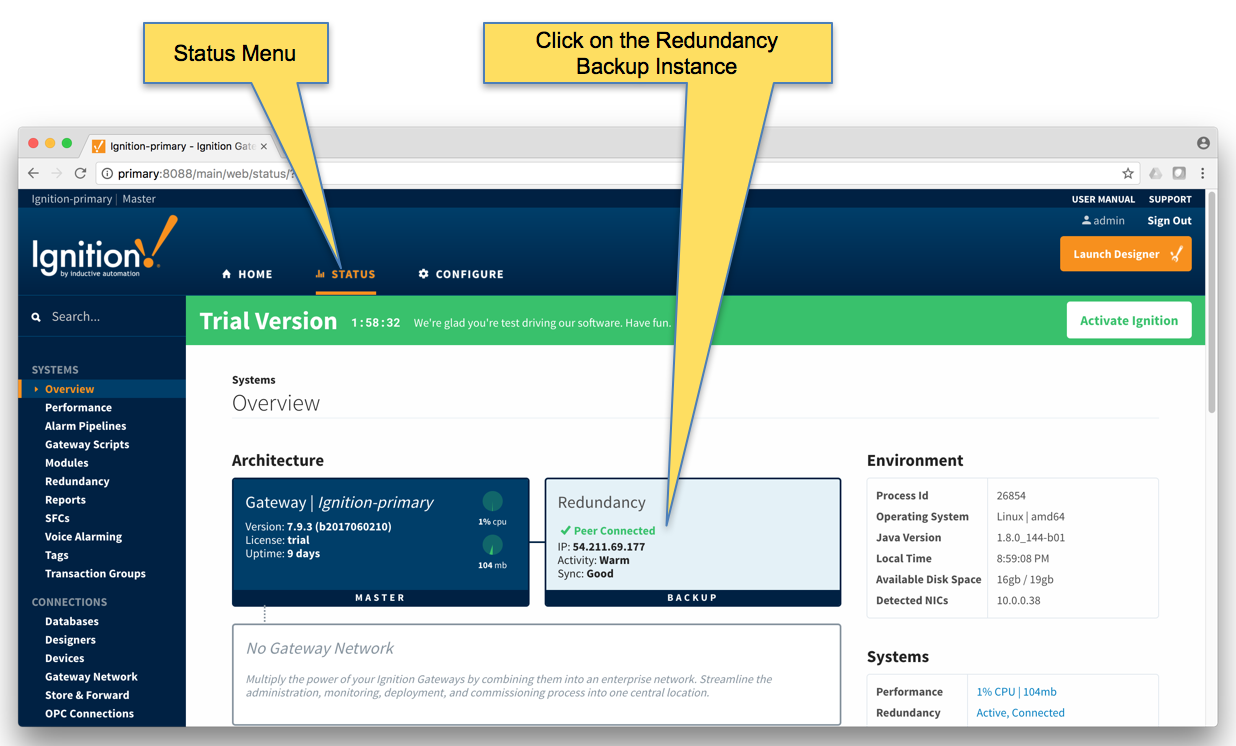 Image Removed
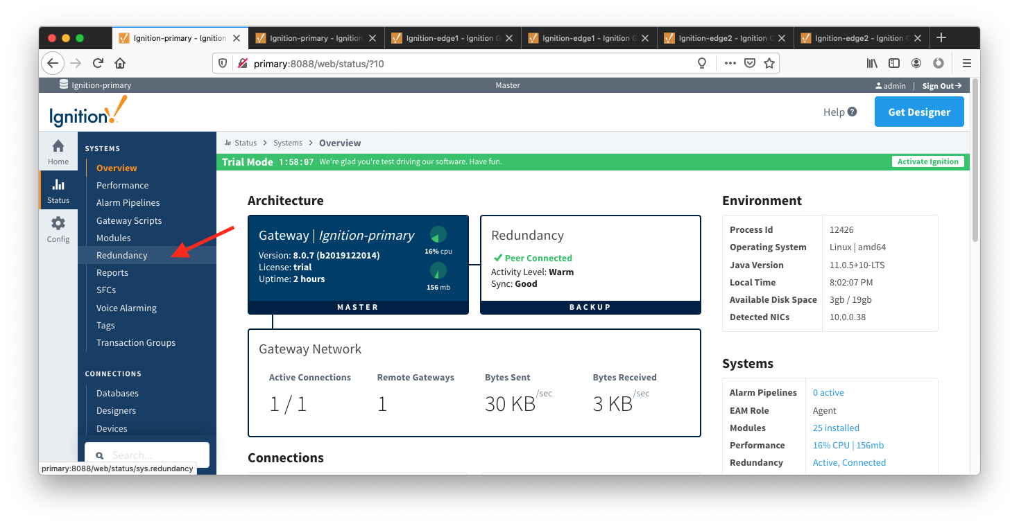 Image Added
- Force the Re-sync via the button below. This will duplicate the master configuration to the backup Ignition instance it is connected to.
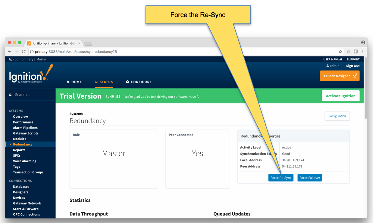 Image Removed
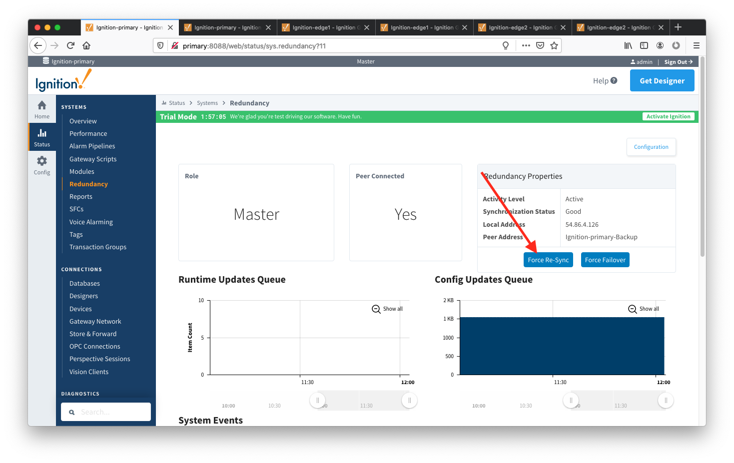 Image Added
- Repeat the above Re-sync steps on the Edge 1 and Edge 2 Ignition instances.
Step 7: Verify MQTT Engine is getting data from the MQTT Transmission Edge 1 and Edge 2
Open Ignition Designer on the Ignition Primary instance. Expand the MQTT Engine tag tree and validate the following tags are present. If they are present and not stale, they are properly connected.
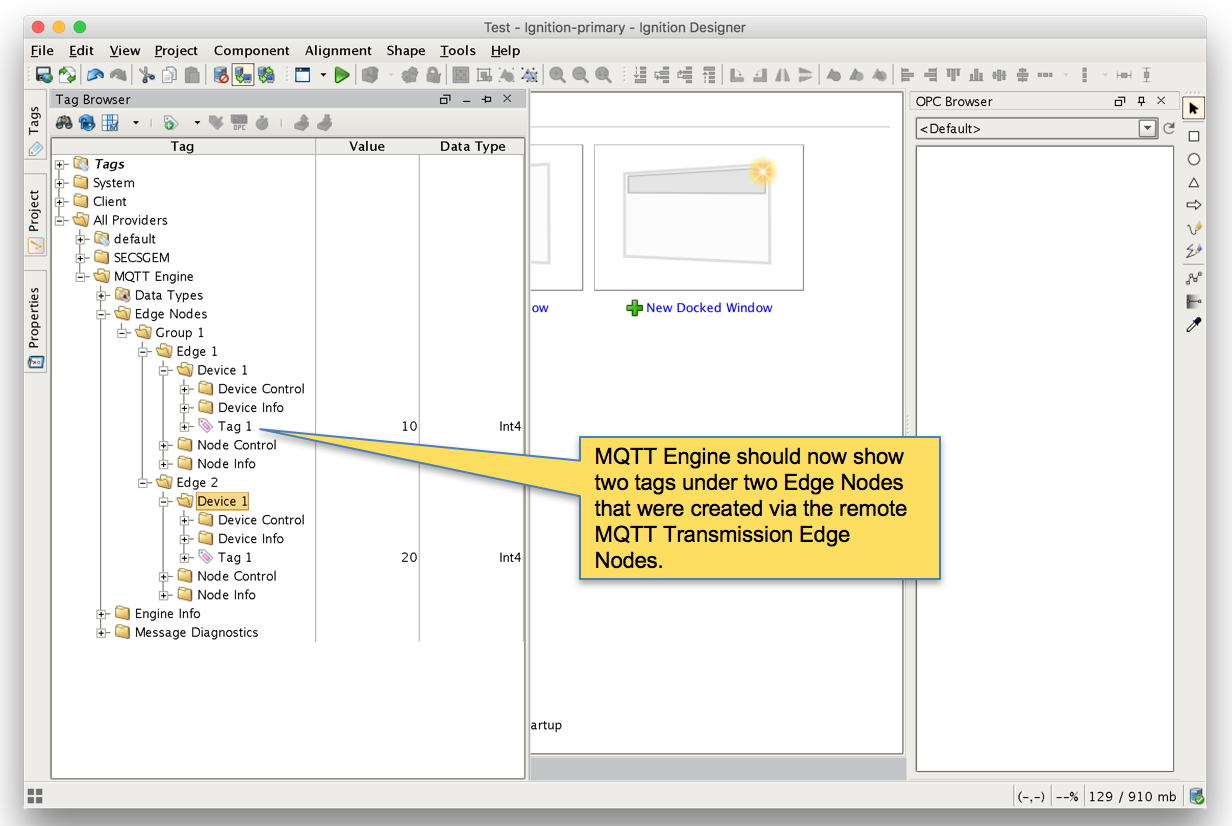 Image Removed
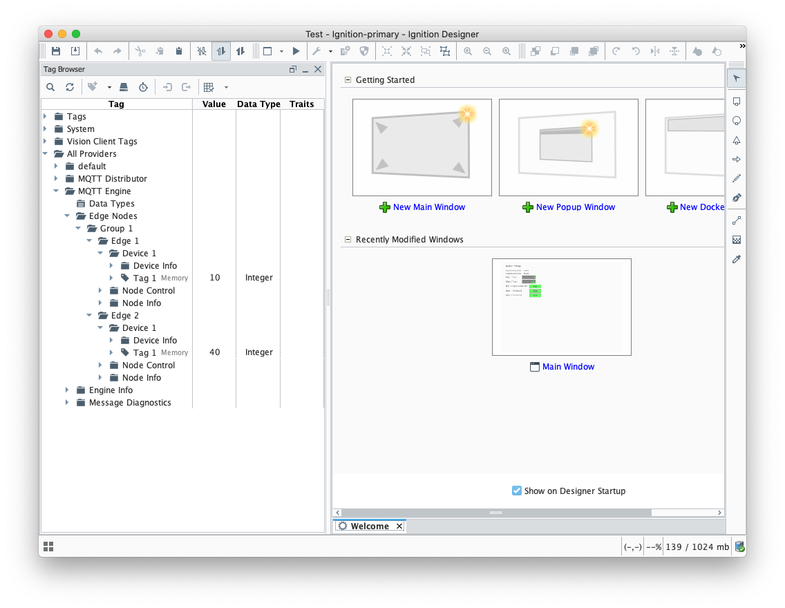 Image Added
Step 8: Test the Redundancy
In order to test the redundancy, we need to make a few simple dashboards. It is important to note that this can not be tested with Ignition Designer alone. Designer can not be opened from an Ignition backup instance since projects get replicated to the backup instances. So, to show everything working, we'll make some very rudimentary dashboards.
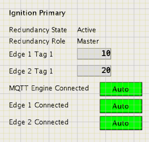
Ignition Primary
- Create the following widgets.
- Label - Ignition Primary
- Label - Redundancy State → Label with Tag Path of "[MQTT Engine]/Engine Info/Redundancy State"
- Label - Redundancy Role → Label with Tag Path of "[MQTT Engine]/Engine Info/Redundancy Role"
- Label - Edge 1 Tag 1 → Label with Tag Path of "[MQTT Engine]/Edge Nodes/Group 1/Edge 1/Device 1/Tag 1"
- Label - Edge 2 Tag 1 → Label with Tag Path of "[MQTT Engine]/Edge Nodes/Group 1/Edge 2/Device 1/Tag 1"
- Label - MQTT Engine Connected → Multi-State Indicator with Tag Path of "[MQTT Engine]/Engine Info/MQTT Clients/Chariot SCADA/Online"
- Label - Edge 1 Connected → Multi-State Indicator with Tag Path of "[MQTT Engine]/Edge Nodes/Group 1/Edge 1/Node Info/Online"
- Label - Edge 2 Connected → Multi-State Indicator with Tag Path of "[MQTT Engine]/Edge Nodes/Group 1/Edge 2/Node Info/Online"
- When complete - it should look similar to what is shown below
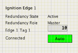
Ignition Edge 1
- Create the following widgets
- Label - Ignition Edge 1
- Label - Redundancy State → Label with Tag Path of "[MQTT Transmission]/Transmission Info/Redundancy State"
- Label - Redundancy Role → Label with Tag Path of "[MQTT Transmission]/Transmission Info/Redundancy Role"
- Label - Edge 1 Tag 1 → Label with Tag Path of "[default]/Edge Nodes/Group 1/Edge 1/Device 1/Tag 1"
- Label - Connected → Multi-State Indicator with Tag Path of "[MQTT Transmission]/Transmission Info/MQTT Clients/Group 1-Edge 1/Online"
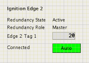
Ignition Edge 2
- Create the following widgets
- Label - Ignition Edge 2
- Label - Redundancy State → Label with Tag Path of "[MQTT Transmission]/Transmission Info/Redundancy State"
- Label - Redundancy Role → Label with Tag Path of "[MQTT Transmission]/Transmission Info/Redundancy Role"
- Label - Edge 2 Tag 1 → Label with Tag Path of "[default]/Edge Nodes/Group 1/Edge 2/Device 1/Tag 1"
- Label - Connected → Multi-State Indicator with Tag Path of "[MQTT Transmission]/Transmission Info/MQTT Clients/Group 1-Edge 2/Online"
- Once all three dashboards have been created, save and publish them and close the Ignition Designer windows.
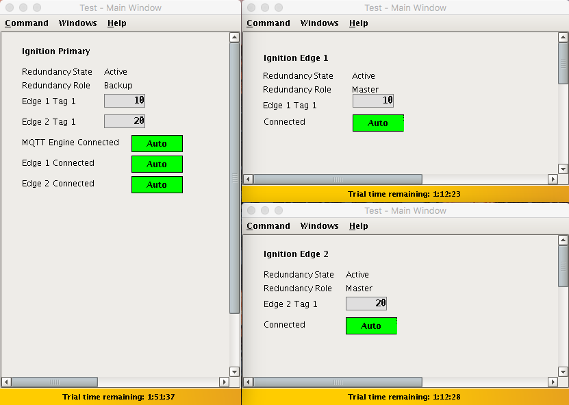
- Now open each of the Ignition client 'Test' projects. With everything running you should see three windows similar to the following.
...
- At this point we can begin failing Ignition instances. From the Status → Redundancy page we can use the 'Force Failover' button as shown below. Of course stopping the actual Ignition instance is another option.
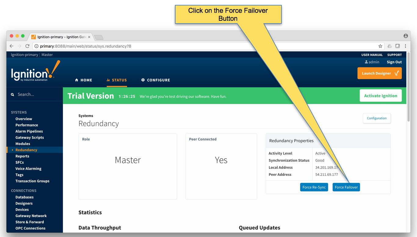 Image Removed
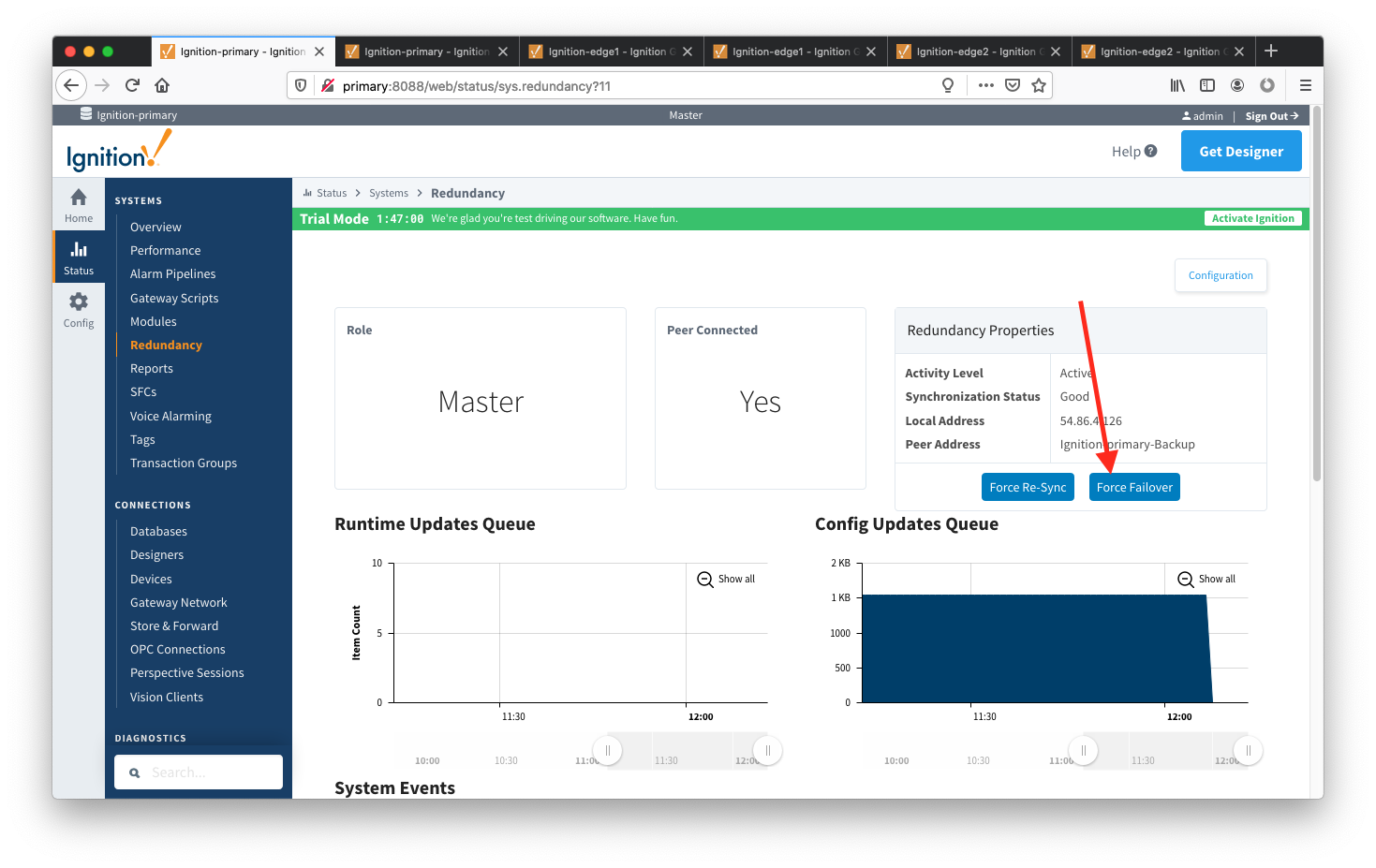 Image Added
Primary Ignition Failure
...
Failing the Ignition Primary instance will cause the following.
- Ignition Primary will go down and be unreachable
- This results in all MQTT connections being lost.
- Ignition Primary Backup will come up and take the place of Ignition Primary
- MQTT Engine will reconnect on Ignition Primary
- The MQTT Transmission instances will reconnect to the new MQTT Server (MQTT Distributor) running in Ignition Primary Backup
- This is all shown in the screenshot below of the Ignition projects. Note all connections are valid and the 'Redundancy Role' of Ignition Primary is now Backup.
Edge 1 Failure
...
Failing the Ignition Edge 1 instance will cause the following.
- Ignition Edge 1 will go down and be unreachable
- This results in the MQTT Connection between Ignition Edge 1 and Ignition Primary being lost.
- Ignition Edge 1 Backup will come up and take the place of Ignition Edge 1.
- The MQTT Transmission instance on Ignition Edge 1 Backup will connect to the MQTT Server (MQTT Distributor) running in Ignition Primary
- This is all shown in the screenshot below of the Ignition projects. Note all connections are valid and the 'Redundancy Role' of Ignition Edge 1 is now Backup.
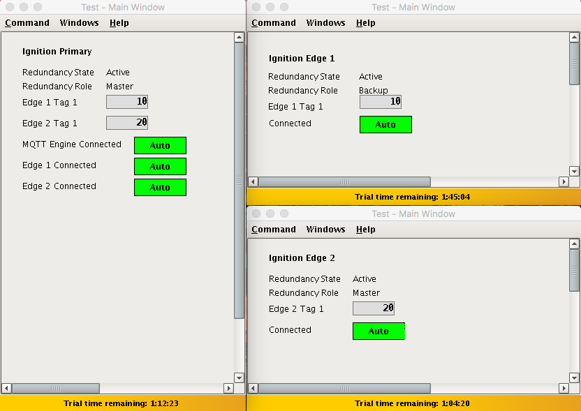 Image Modified
Failure of all Master Nodes
...
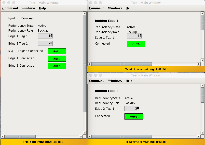
Failing all master Ignition instances (Primary, Edge 1, and Edge 2) will cause the following.
- Ignition Primary, Edge 1, and Edge 2 will all go down and be unreachable
- This results in all MQTT connections being lost
- Ignition Primary Backup, Edge 1 Backup, and Edge 2 Backup will all come up and start their MQTT services.
- The new MQTT Transmission instances on Ignition Edge 1 Backup and Ignition Edge 2 Backup will connect to the new MQTT Server (MQTT Distributor) running in Ignition Primary Backup
- This is all shown in the screenshot below of the Ignition projects. Note all connections are valid and the 'Redundancy Role' of all instances is now Backup.
To summarize, this tutorial shows how Ignition and the MQTT Modules can be used to create a resilient infrastructure that is able to withstand failures of machines and network connections within the architecture. As noted earlier, this tutorial shows the basic requirements of configuring failover support with Ignition and the MQTT Modules. This can be further improved with additional advanced concepts. Feel free to contact sales@cirrus-link.com for more information.
...