Versions Compared

Key

  • This line was added.
  • This line was removed.
  • Formatting was changed.

...

For the purposes of this document there are some definitions that are explained below.

EFM EMERSON ROC → Settings

  • Global TLP Definitions (Global)
    • The
    • These are the global TLP definitions made available to the EFM Emerson ROC module.  They are uploaded to the Ignition instance in the form of specifically formatted CSV files.  These TLP definitions can be reference by the configurations of the individual ROC devices that they apply to. A single Ignition Gateway may contain multiple global TLP definitions files that are used to configure different device types where the actual point types & parameters of the individual TLPs may differ across the different files and device types.
  • Device TLP Definitions
    • These are a subset of the global TLP definition files that apply to a specific device.
  • TLP Templates
    • TLP templates are logical groupings of TLPs.  Generally TLP templates would be created so that instances of them can be used by specifying a poll group with a logical number (the 'L' parameter in a TLP).
  • TLP Poll Groups
    • Poll groups use TLP templates in conjunction with a logical number to create a specific set of TLPs to be polled at a specified poll rate.

There are six basic steps to getting all of the data available from a ROC into Ignition

  1. Define the global TLP definitions available for all ROC devices in this Ignition instance
  2. Create the base device connection to the ROC
  3. Specify the subset of TLP definitions that this specific ROC uses
  4. Create TLP Template(s) which define groups of TLPs should be polled as a logical group
  5. Create TLP Poll Group(s) which specify the logical parameters associated with a given TLP Template
  6. Use Ignition Designer to pull tags into a tag provider

Global TLP Definitions

The EFM Emerson ROC driver module provides a configuration section to the Ignition Gateway.  These can be seen in the Configure section of the Ignition Gateway web UI on the left panel near the bottom.  Note this step is required before any EFM Emerson ROC device connections can be define.  Each Emerson ROC device connection will use a subset of these global TLP definitions to operate.

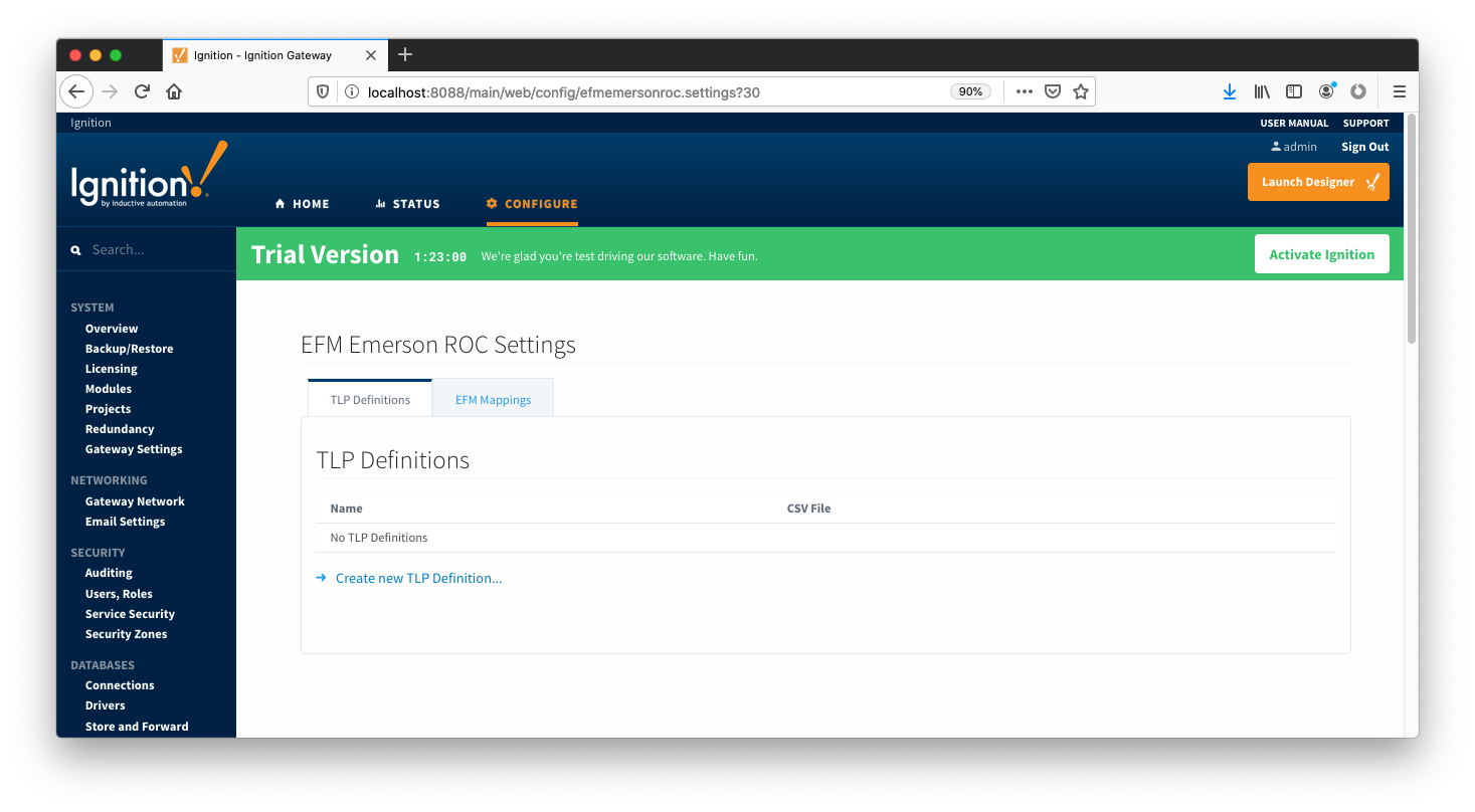
Once in the configuration screen there will be a link to create new global TLP definitions.  Click the link shown below to create a new one.

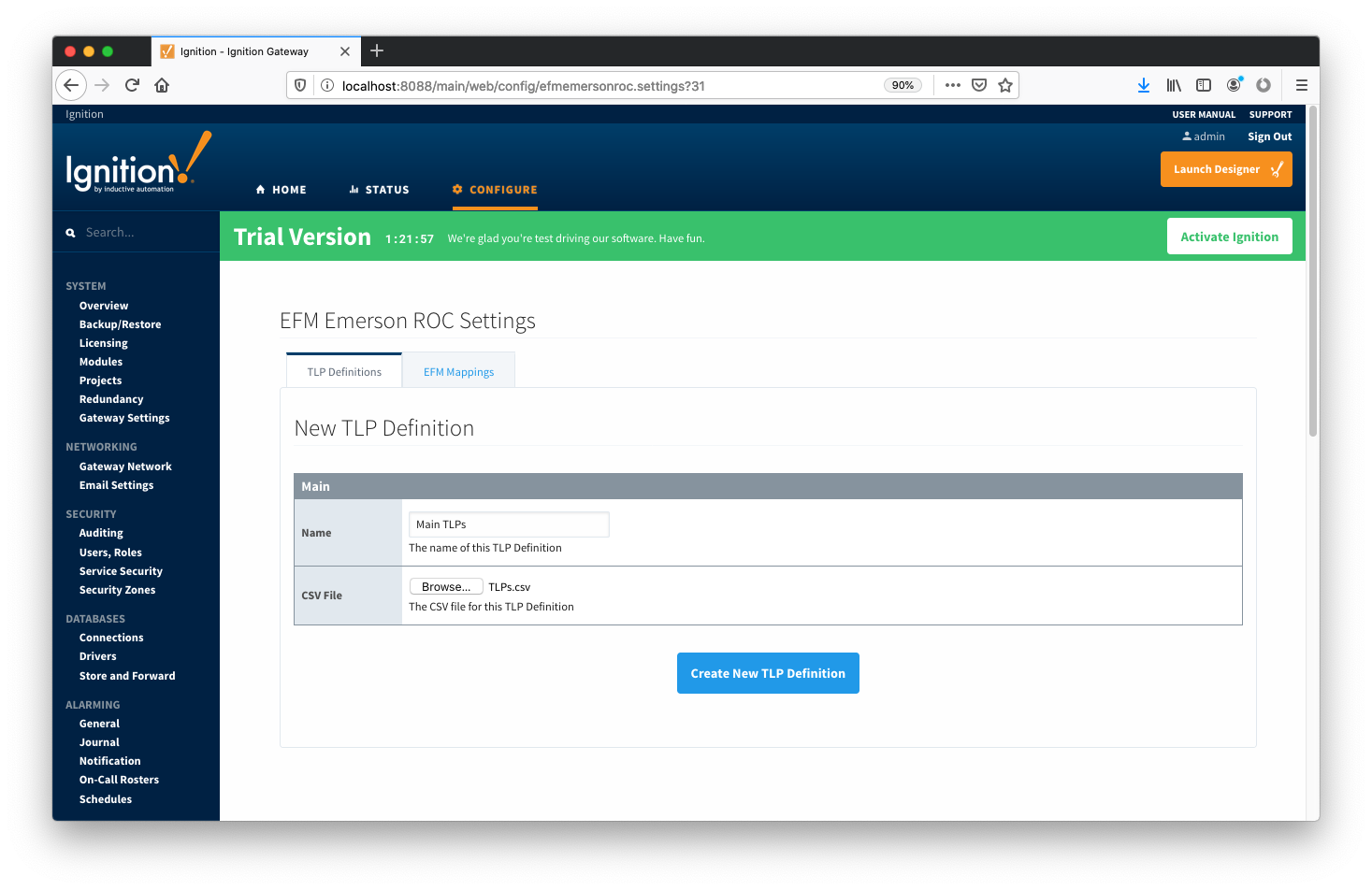
Image RemovedWhen creating a new global TLP definition only a name and a CSV file needs to be specified.  The name can be any unique name that describes the TLPs included in that CSV file.  They can be device specific TLPs or they can be TLPs associated with a specific user program.

Image RemovedThe headers of the CSV file must be as follows:

  • EFM Mappings
    • Configuration Mappings
      • The configuration mapping files are used for building up EFM Configuration Records. They define which TLPs map to which fields (columns) in an EFM Configuration Record.  Additionally they can provide bit and/or value mappings for the TLP values. They are uploaded to the Ignition instance in the form of specifically formatted CSV files. 
    • Periodic Mappings
      • The periodic mapping files are used for building up EFM Periodic History Records.  They define which TLPs map to which fields (columns) in an EFM Periodic History Record, the logical type of the point type table (meter, station, or input), and an archive type of the value. They are uploaded to the Ignition instance in the form of specifically formatted CSV files. 

OPC-UA SERVER → Devices 

  • TLP Definitions (Device)
    • These are a subset of the global TLP definition files that apply to a specific device.
  • TLP Templates
    • TLP templates are logical groupings of TLPs.  Generally TLP templates would be created so that instances of them can be used by specifying a poll group with a logical number (the 'L' parameter in a TLP).
  • TLP Poll Groups
    • Poll groups use TLP templates in conjunction with a logical number to create a specific set of TLPs to be polled at a specified poll rate.


There are six basic steps to getting all of the data available from a ROC into Ignition

  1. Define/upload the global TLP definitions available for all ROC devices in this Ignition instance
  2. Define/upload the EFM Mappings for all ROC devices in this Ignition Instance
  3. Create the base device connection to the ROC
  4. Specify the subset of TLP definitions that this specific ROC uses
  5. Create TLP Template(s) which define groups of TLPs should be polled as a logical group
  6. Create TLP Poll Group(s) which specify the logical parameters associated with a given TLP Template
  7. Use Ignition Designer to pull tags into a tag provider

Global TLP Definitions

The EFM Emerson ROC driver module provides a configuration section to the Ignition Gateway.  These can be seen in the Configure section of the Ignition Gateway web UI on the left panel near the bottom.  Note this step is required before any EFM Emerson ROC device connections can be define.  Each Emerson ROC device connection will use a subset of these global TLP definitions to operate.

Once in the configuration screen there will be a link to create new global TLP definitions.  Click the link shown below to create a new one.

Image AddedWhen creating a new global TLP definition only a name and a CSV file needs to be specified.  The name can be any unique name that describes the TLPs included in that CSV file.  They can be device specific TLPs or they can be TLPs associated with a specific user program.

Image AddedThe headers of the CSV file must be as follows:

  • Point Type #
    • The 'T' parameter of a TLP - must be an integer
  • Point Type Description
    • A long description of the 'T' parameter
  • Point Type Abbreviation
    • The abbreviation of the 'T' parameter
  • Parameter Number
    • The 'P' parameter of the TLP - must be an integer
  • Parameter Name
    • The descriptive name of the TLP
  • Parameter Description
    • The description of the TLP
  • Parameter Abbreviation
    • This becomes the default tag name of the parameter in Ignition.  It can be changed in any TLP template where it is defined.
  • Access
    • The access value for the TLP.  Must be either R/O or R/W
  • DataType
    • The datatype of the TLP.  Must be one of the following:
      • BIN
        • Binary value
        • 1 byte
        • Ignition Type: Byte
      • AC
        • ASCII String Value
        • Variable number of bytes
        • Ignition Type: String
      • INT8
        • Signed 8-bit Value
        • 1 byte
        • Ignition Type: Short
      • INT16
        • Signed 16-bit Value
        • 2 bytes
        • Ignition Type: Short
      • INT32
        • Signed 32-bit Value
        • 4 bytes
        • Ignition Type: Integer
      • UINT8
        • Unsigned 8-bit Value
        • 1 byte
        • Ignition Type: Short
      • UINT16
        • Unsigned 16-bit Value
        • 2 bytes
        • Ignition Type: Integer
      • UINT32
        • Unsigned 32-bit Value
        • 4 bytes
        • Ignition Type: Long
      • FL
        • 4-byte Floating-Point Value
        • 4 bytes
        • Ignition Type: Float
      • FLP
        • Same as FL
        • 4-byte Floating-Point Value
        • 4 bytes
        • Ignition Type: Float
      • DBL
        • 8-byte Floating-Point Value
        • 8 bytes
        • Ignition Type: Double
      • TIME
        • 4 byte
  • Point Type #
    • The 'T' parameter of a TLP - must be an integer
  • Point Type Description
    • A long description of the 'T' parameter
  • Point Type Abbreviation
    • The abbreviation of the 'T' parameter
  • Parameter Number
    • The 'P' parameter of the TLP - must be an integer
  • Parameter Name
    • The descriptive name of the TLP
  • Parameter Description
    • The description of the TLP
  • Parameter Abbreviation
    • This becomes the default tag name of the parameter in Ignition.  It can be changed in any TLP template where it is defined.
  • Access
    • The access value for the TLP.  Must be either R/O or R/W
  • DataType
    • The datatype of the TLP.  Must be one of the following:
      • BIN
        • Binary value
        • 1 byte
        • Ignition Type: Byte
      • AC
        • ASCII String Value
        • Variable number of bytes
        • Ignition Type: String
      • INT8
        • Signed 8-bit Value
        • 1 byte
        • Ignition Type: Short
      • INT16
        • Signed 16-bit Value
        • 2 bytes
        • Ignition Type: Short
      • INT32
        • Signed 32-bit Value
        • 4 bytes
        • Ignition Type: Integer
      • UINT8
        • Unsigned 8-bit Value
        • 1 byte
        • Ignition Type: Short
      • UINT16
        • Unsigned 16-bit Value
        • 2 bytes
        • Ignition Type: Integer
      • UINT32
        • Unsigned 32-bit Value
        • 4 bytes
        • Ignition Type: Long
      • FL
        • 4-byte Floating-Point Value
        • 4 bytes
        • Ignition Type: Float
      • FLP
        • Same as FL
        • 4-byte Floating-Point Value
        • 4 bytes
        • Ignition Type: Float
      • DBL
        • 8-byte Floating-Point Value
        • 8 bytes
        • Ignition Type: Double
      • TIME
        • 4 byte ROC representation of time
      • TLP
        • 3 byte ROC representation of a TLP
      • HOURMINUTE
        • 2 byte ROC representation of hour and minute
      • FLOAT
        • Same as FL
        • 4-byte Floating-Point Value
        • 4 bytes
        • Ignition Type: Float
      • DOUBLE
        • Same as DBL
        • 8-byte Floating-Point Value
        • 8 bytes
        • Ignition Type: Double
      • DT6
        • 6 byte ROC representation of time
  • Length
    • The length of the the value.  For example INT8 is 1, INT16 is 2, for an AC type it is variable and dependent on the specific TLP.

Below is an example of a properly formatted global TLP CSV file:

Point Type #,Point Type Description,Point Type Abbreviation,Parameter Number,Parameter Name,Parameter Description,Parameter Abbreviation,Access,DataType,Length
1,Discrete Inputs,DIN,0,Point Tag ID,,TAG,R/W,AC,10
1,Discrete Inputs,DIN,1,Filter,,FILTER,R/W,UINT8,1
1,Discrete Inputs,DIN,2,Status,,STATUS,R/W,UINT8,1
1,Discrete Inputs,DIN,3,Mode,,MODE,R/W,BIN,1
1,Discrete Inputs,DIN,4,Alarm Code,,ALARM,R/O,BIN,1
1,Discrete Inputs,DIN,5,Accumulated Value,,ACCUM,R/W,UINT32,4
1,Discrete Inputs,DIN,6,On Counter,,ONCTR,R/W,UINT32,4
1,Discrete Inputs,DIN,7,Off Counter,,OFFCTR,R/W,UINT32,4
1,Discrete Inputs,DIN,8,0% Pulse Width,,MINCNT,R/W,INT16,2
1,Discrete Inputs,DIN,9,100% Pulse Width,,MAXCNT,R/W,INT16,2

An example global TLPs file can be found here: TLPs.csv

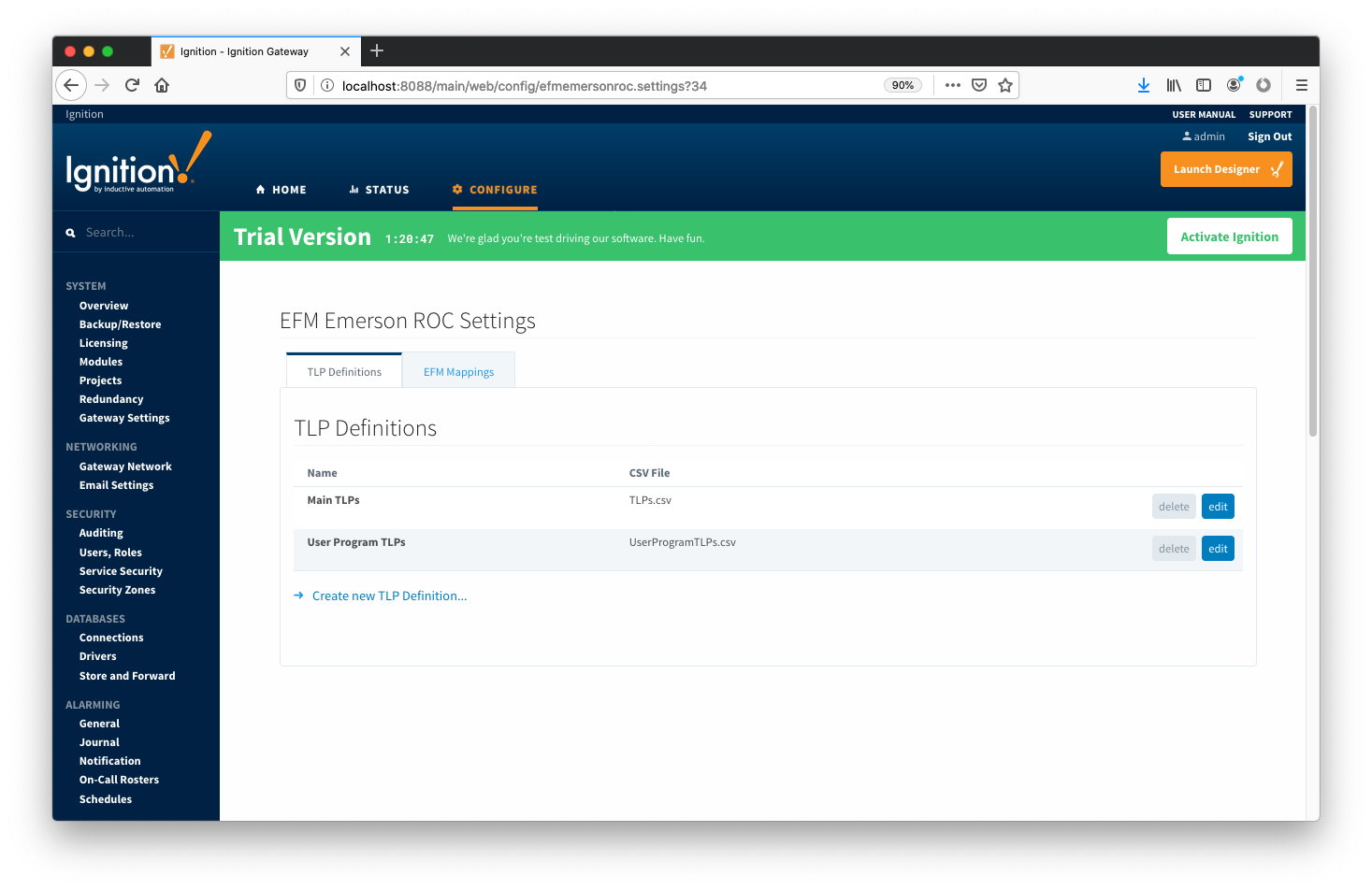
This can be uploaded to the Emerson ROC driver configuration and called 'Main TLPs'.  Once complete, it will look similar to what is shown below.

    • .  For example INT8 is 1, INT16 is 2, for an AC type it is variable and dependent on the specific TLP.


Below is an example of a properly formatted global TLP CSV file:

No Format
Point Type #,Point Type Description,Point Type Abbreviation,Parameter Number,Parameter Name,Parameter Description,Parameter Abbreviation,Access,DataType,Length
1,Discrete Inputs,DIN,0,Point Tag ID,,TAG,R/W,AC,10
1,Discrete Inputs,DIN,1,Filter,,FILTER,R/W,UINT8,1
1,Discrete Inputs,DIN,2,Status,,STATUS,R/W,UINT8,1
1,Discrete Inputs,DIN,3,Mode,,MODE,R/W,BIN,1
1,Discrete Inputs,DIN,4,Alarm Code,,ALARM,R/O,BIN,1
1,Discrete Inputs,DIN,5,Accumulated Value,,ACCUM,R/W,UINT32,4
1,Discrete Inputs,DIN,6,On Counter,,ONCTR,R/W,UINT32,4
1,Discrete Inputs,DIN,7,Off Counter,,OFFCTR,R/W,UINT32,4
1,Discrete Inputs,DIN,8,0% Pulse Width,,MINCNT,R/W,INT16,2
1,Discrete Inputs,DIN,9,100% Pulse Width,,MAXCNT,R/W,INT16,2

An example global TLPs file can be found here: TLPs.csv

This can be uploaded to the Emerson ROC driver configuration and called 'Main TLPs'.  Once complete, it will look similar to what is shown below.

Image Added

EFM Mappings

Configuration Mappings

The configuration mapping files are used for building up EFM Configuration Records.  They define which TLPs map to which fields (columns) in an EFM Configuration Record.  Additionally they can provide bit and/or value mappings for the TLP values. 

These mappings are CSV files with the following values:

  • Column Name
    • The name of the EFM Configuration Record field
  • Column Data Type
    • The datatype of the EFM Configuration Record. Must be one of the following:
      • VARCHAR
      • INTEGER
  • TLP Point Type
    • The 'T' parameter of a TLP - must be an integer
  • TLP Parameter Number
    • The 'P' parameter of a TLP - must be an integer
  • Bits
    • An optional declaration of the bits to use from the value of the TLP
    • An ordered, colon-delimited, list of bit positions
    • Examples:
      • If the TLP value is a byte and only the first (least significant) bit is used, this value would be: 0
      • If the TLP value is a byte and the 2nd and 3rd bits are used, this value would be: 2:3
  • Event Value Mapping
    • An optional mapping of the TLP values to the values that will be stored in the EFM Event Record
    • If using only certain bits the values will need to be ordered, colon-delimited. lists of bit values
  • Config Value Mapping
    • An optional mapping of the TLP values to the values that will be stored in the EFM Configuration Record
    • If using only certain bits the values will need to be ordered, colon-delimited, lists of bit values

Below is an example of a properly formatted Configuration Mapping file:

No Format
mtr_point_tag,VARCHAR,46,0,,,
mtr_description,VARCHAR,46,1,,,
mtr_serial,VARCHAR,46,0,,,
plate_dia,NUMBER,46,10,,,
plate_temp,NUMBER,46,11,,,
plate_mat,VARCHAR,46,12,,,0=Stainless;1=Monel;2=Carbon;3=304 SS;4=316 SS;5=Monel 400
k_fctr,NUMBER,46,43,,,
pipe_dia,NUMBER,46,7,,,
pipe_temp,NUMBER,46,8,,,
pipe_mat,VARCHAR,46,9,,,0=Stainless;1=Monel;2=Carbon;3=304 SS;4=316 SS;5=Monel 400
atmos_press,NUMBER,46,15,,,
alt,NUMBER,46,20,,,
lat,NUMBER,46,21,,,
base_press,NUMBER,46,13,,,
base_temp,NUMBER,46,14,,,
cntrct_hr,NUMBER,15,10,,,
calc_mthd,VARCHAR,47,72,,,AGA3-92=AGA-3 1992;AGA7-96=AGA-7
fpv_mthd,VARCHAR,47,73,,,AGA8-92 Gross 1=AGA-8 Gross 1 1992;AGA8-92 Detailed=AGA-8 Detail 1992
mtr_taps,VARCHAR,46,4,0,,0=Flange;1=Pipe
sp_tap,VARCHAR,46,4,2,,0=Downstream;1=Upstream
sp_typ,VARCHAR,46,4,3,,0=Gauge;1=Absolute
mtr_typ,VARCHAR,46,2,1,,0=Orifice;1=Turbine
live_analysis,VARCHAR,46,3,5,,0=No;1=Yes
live_btu,VARCHAR,46,4,4,,0=Yes;1=No
live_grav,VARCHAR,46,4,1,,0=Yes;1=No
lo_flo_ctoff,NUMBER,46,43,,,
specf_heat_ratio,NUMBER,46,19,,,
btu_base,VARCHAR,46,3,3:4,0:0=0;0:1=1;1:0=2;1:1=3,0:0=Dry;0:1=As Delivered;1:0=Wet;1:1=As Delivered
mass_heating_val,NUMBER,46,17,,,
specf_gravity,NUMBER,46,16,,,
viscosity,NUMBER,46,18,,,
carbon_dioxide,NUMBER,46,24,,,
nitrogen,NUMBER,46,23,,,
methane,NUMBER,46,28,,,
ethane,NUMBER,46,29,,,
propane,NUMBER,46,30,,,
isobutane,NUMBER,46,32,,,
butane,NUMBER,46,31,,,
isopentane,NUMBER,46,34,,,
pentane,NUMBER,46,33,,,
hexane,NUMBER,46,35,,,
heptane,NUMBER,46,36,,,
octane,NUMBER,46,37,,,
nonane,NUMBER,46,38,,,
decane,NUMBER,46,39,,,
oxygen,NUMBER,46,40,,,
water,NUMBER,46,26,,,
hydrogen_sulfide,NUMBER,46,25,,,
helium,NUMBER,46,27,,,
hydrogen,NUMBER,46,42,,,
carbon_monoxide,NUMBER,46,41,,,
argon,NUMBER,46,85,,,


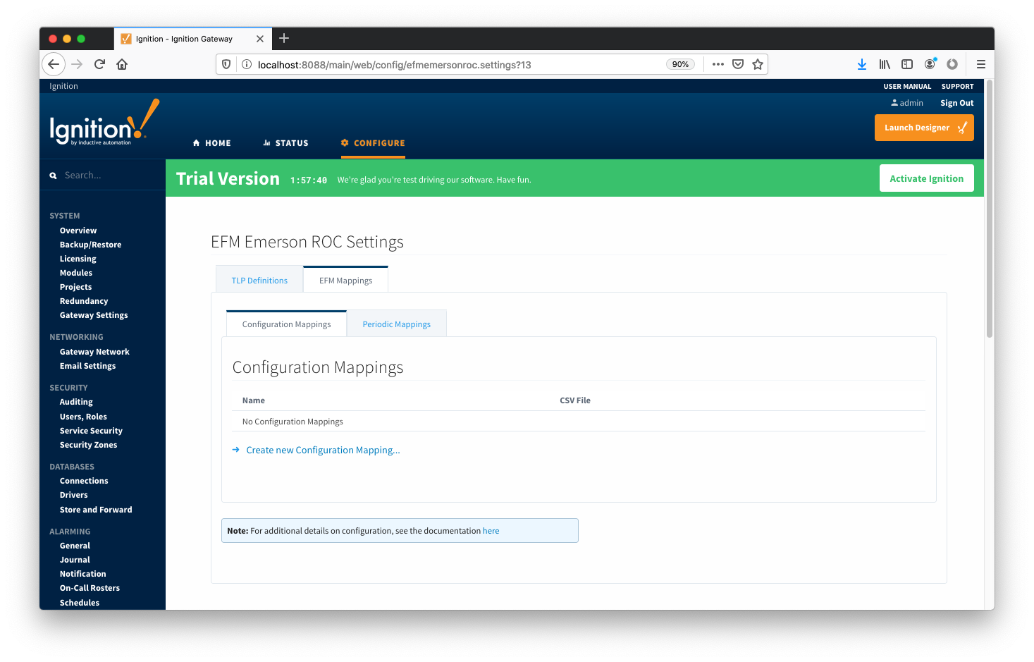
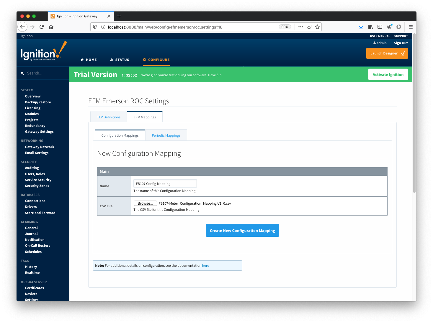
The Configuration Mappings tab shows all uploaded Configuration Mapping files.

Image AddedA new Configuration Mapping can be added by clicking on the "Create New Configuration Mapping..." link.

Image AddedImage Removed

At this point device connections can be created using these global TLP definitions.

...