...
TLPs are polled at a specified interval based on a poll rate and then made available via the OPC-UA interface. Alarms, events, and history are made available to MQTT Transmission to be published as immutable record Record objects to an MQTT server. Typically these would be received by the MQTT Engine and MQTT Recorder modules running on a central Ignition Gateway and inserted into a database for later use or to be made available to other third party systems.
...
- Global TLP Definitions
- These are the global TLP definitions made available to the Ignition instanceEFM Emerson ROC module. They are uploaded to the Ignition instance in the form of specifically formatted CSV filefiles. These TLP definitions can then be referenced by a specific instance of a ROC device connection to restrict the TLP definitions to those that apply to that device. For example, lets say four Global TLP definitions are uploaded. Lets say these are ROC800.csv, FLOBOSS107.csv, UserProgram1.csv, and UserProgram2.csv. With these global definitions there could be differing definitions for any specific T/P combination. This is only allowed if the differing definitions are in different CSV files. No individual CSV file is allowed to have differing definitions of the same T/P combination.
- Device TLP Definitions
- These are a subset of the global TLP definitions that apply to this specific device. Continuing with the example from above let's say this is a ROC 800 and has User Program 1 installed. ROC800.csv and UserProgram1.csv could be selected as the TLP definitions that apply to this specific ROC device.
- TLP Templates
- TLP templates are groupings of TLPs that represent logical groupings of TLPs. Generally TLP templates would be created so that instances of them can be used by specifying a poll group with a logical number or the 'L' parameter in a TLP.
- reference by the configurations of the individual ROC devices that they apply to. A single Ignition Gateway may contain multiple global TLP definitions files that are used to configure different device types where the actual point types & parameters of the individual TLPs may differ across the different files and device types.
- Device TLP Definitions
- These are a subset of the global TLP definition files that apply to a specific device.
- TLP Templates
- TLP templates are logical groupings of TLPs. Generally TLP templates would be created so that instances of them can be used by specifying a poll group with a logical number (the 'L' parameter in a TLP).
- TLP Poll Groups
- Poll groups use TLP templates in conjunction with a logical number to create a specific set of TLPs to be polled at a specified
TLP Poll Groups- Poll groups use TLP templates in conjunction with a logical number to create a specific set of TLPs to be polled at a specified poll rate.
There are six basic steps to getting all of the data available from a ROC into Ignition
...
The EFM Emerson ROC driver module provides a configuration section to the Ignition Gateway. These can be seen in the Configure section of the Ignition Gateway web UI on the left panel near the bottom. Note this step is required before any EFM Emerson ROC device connections can be define. Each Emerson ROC device connection will use a subset of these global TLP definitions to operate.
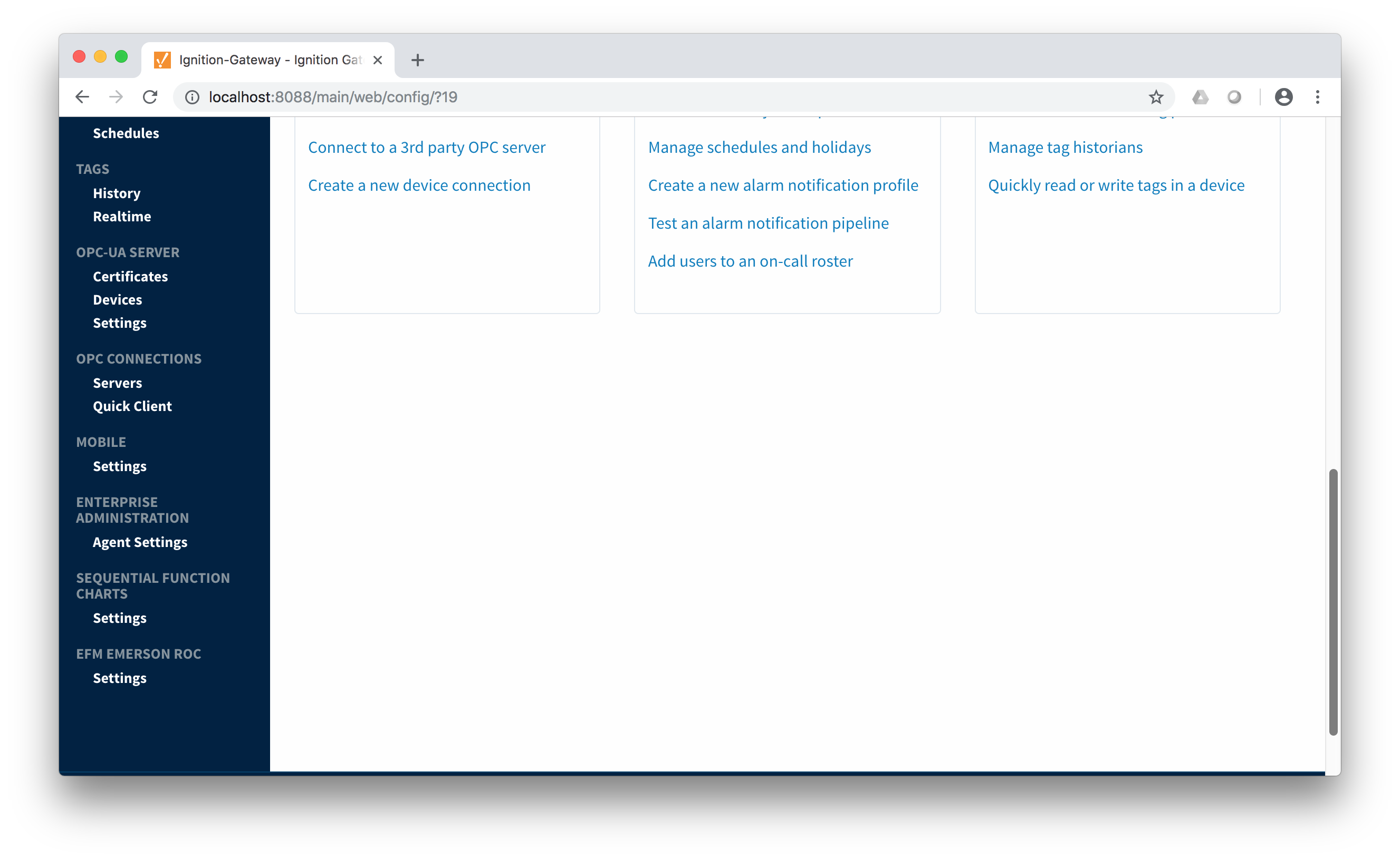 Image Removed
Once Once in the configuration screen there will be a link to create new global TLP definitions. Click the link shown below to create a new one.
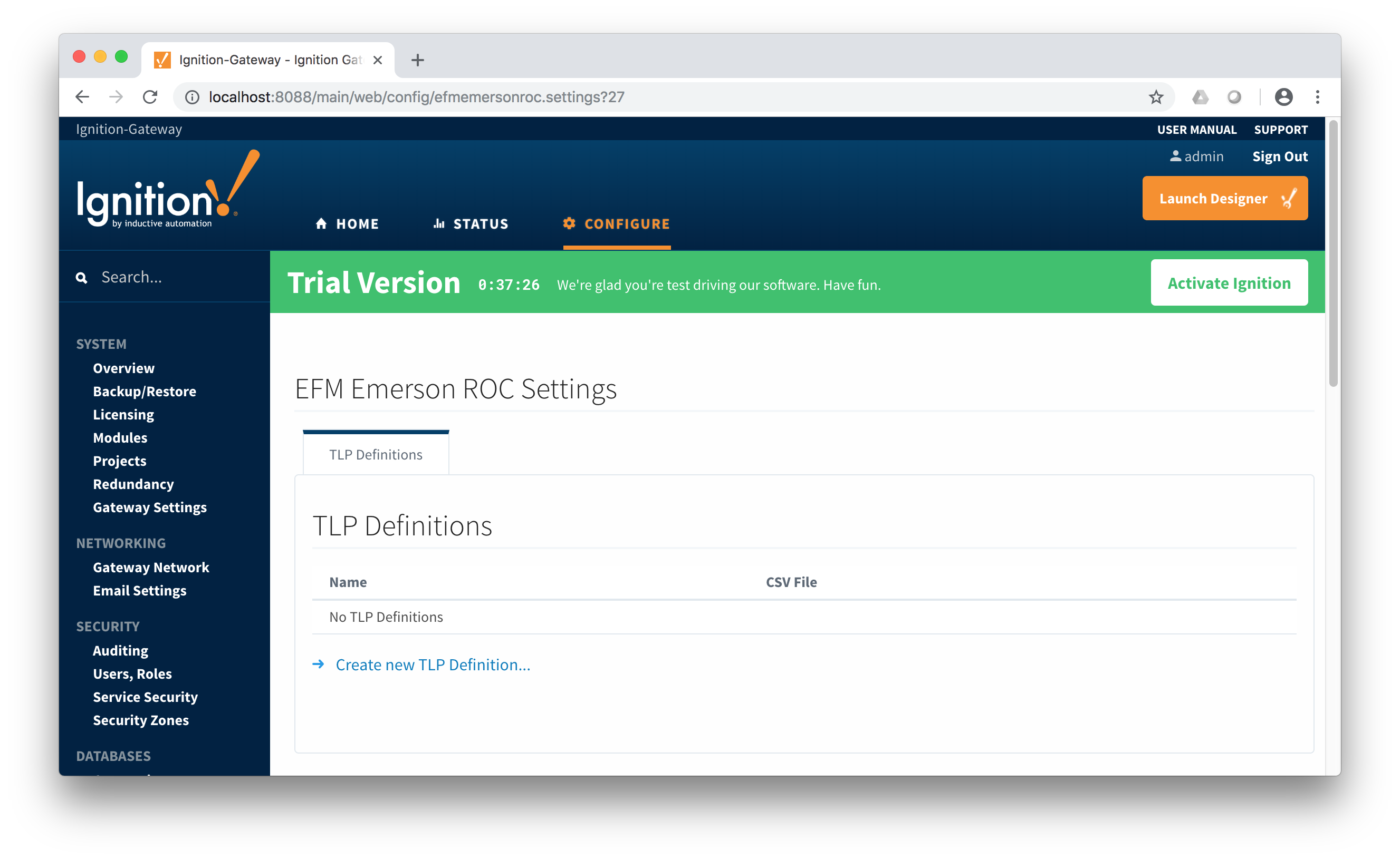 Image Removed
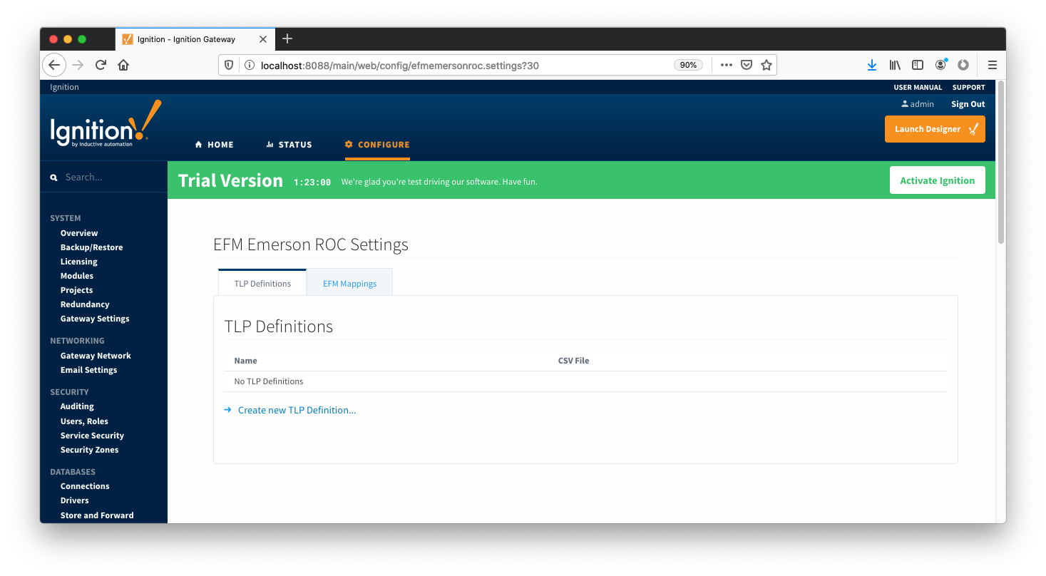 Image AddedWhen creating a new global TLP definition only a name and a CSV file needs to be specified. The name can be any unique name that describes the TLPs included in that CSV file. They can be device specific TLPs or they can be TLPs associated with a specific user program.
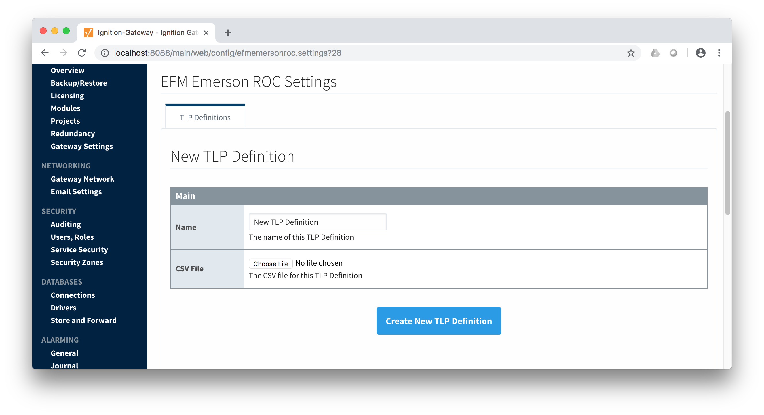 Image Removed
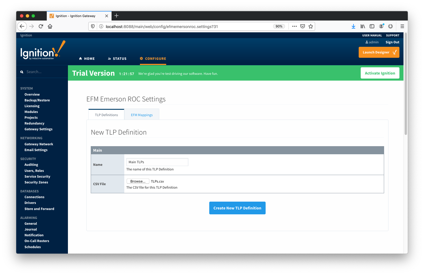 Image AddedThe headers of the CSV file must be as follows:
...
An example global TLPs file can be found here:| View file |
|---|
name | TLPs.csvheight250 | This can be uploaded to the Emerson ROC driver configuration and called 'Main TLPs'. Once complete, it will look similar to what is shown below.
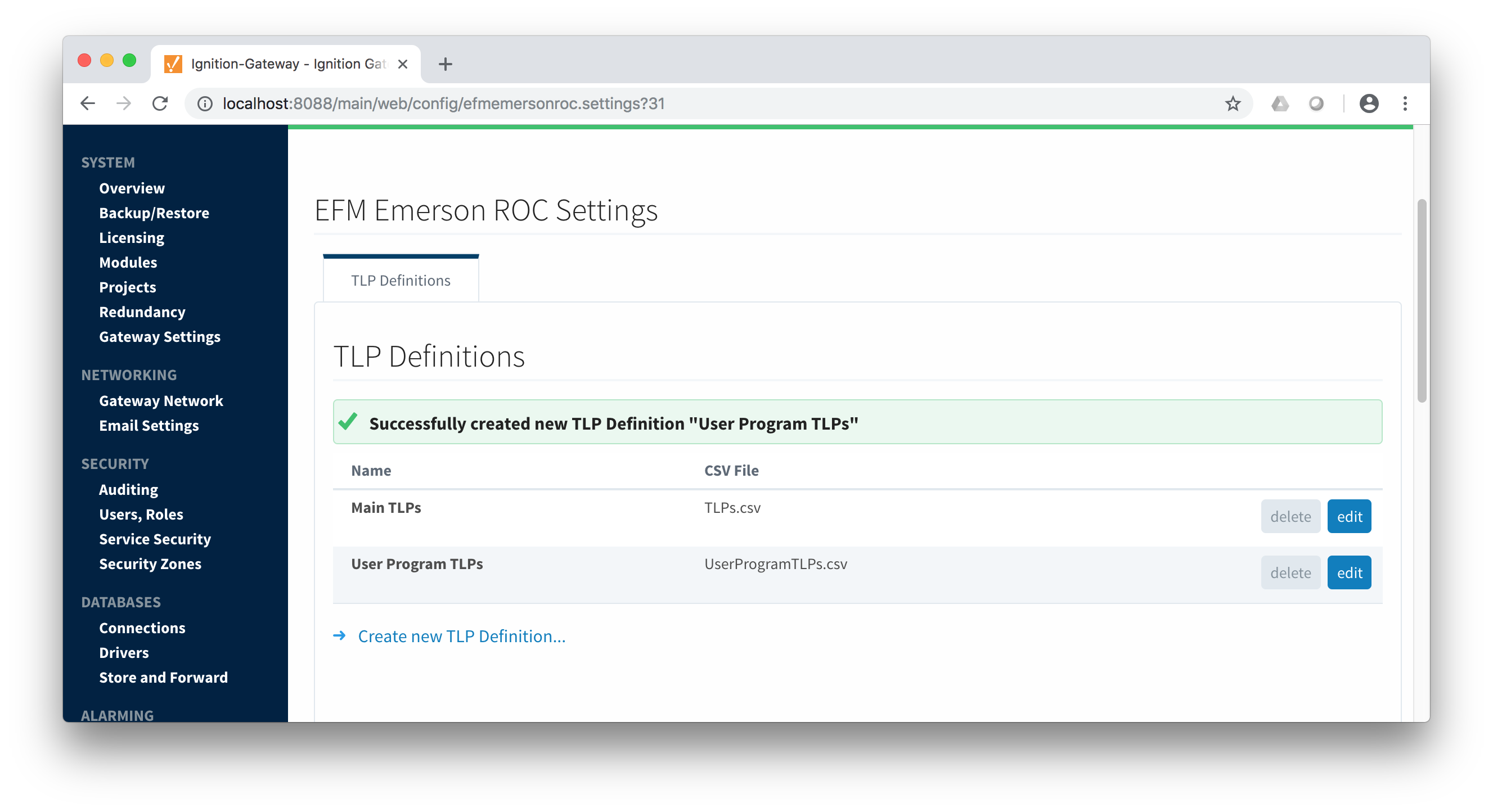 Image Removed
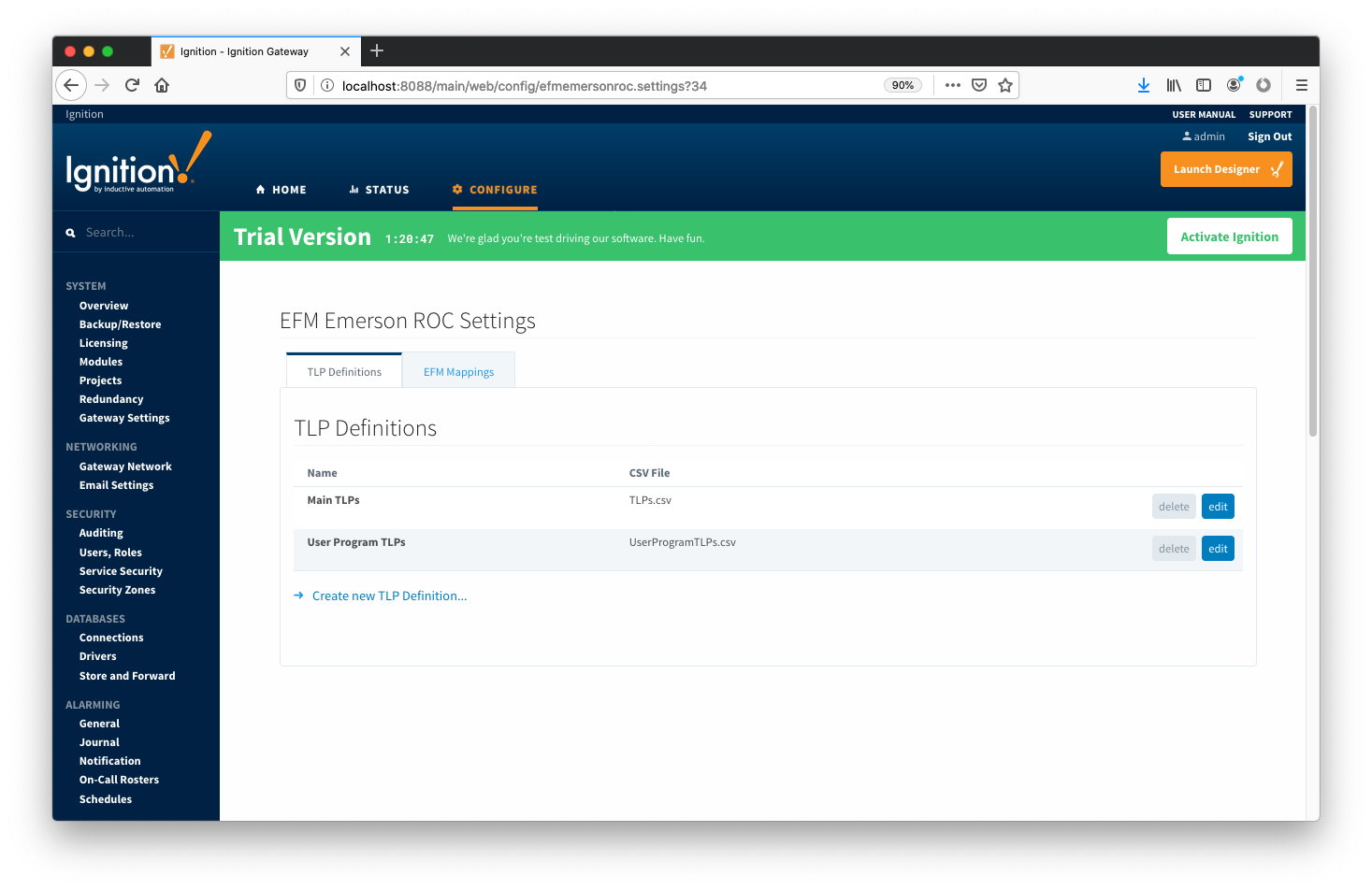 Image Added
At this point device connections can be created using these global TLP definitions.
...
Configuring an Emerson ROC device connection is done as is with any other driver using the OPC-UA interface. Begin by clicking the Configure tab at the top of the Ignition Gateway web UI and scrolling down to the OPC-UA Server's Devices section and clicking it as shown below.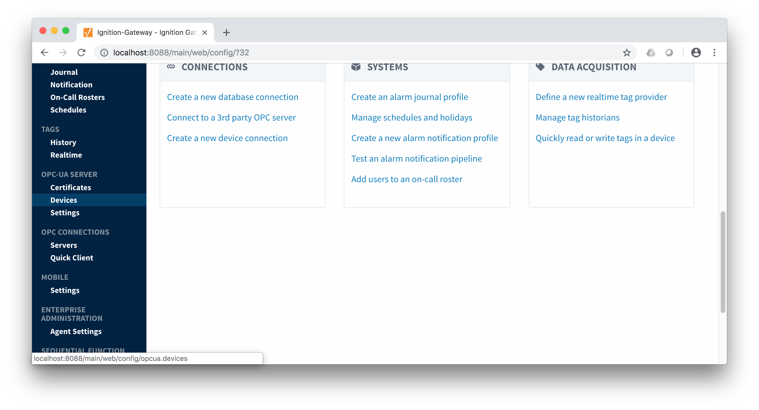 Image Removed
Once done you will see the following. Click the 'Create new Device...' link to create the Emerson ROC device connection.
 Image RemovedAfter clicking the 'Create new Device...' link you will see the following. Select the 'EFM Emerson ROC' and click 'Next' at the bottom of the page.
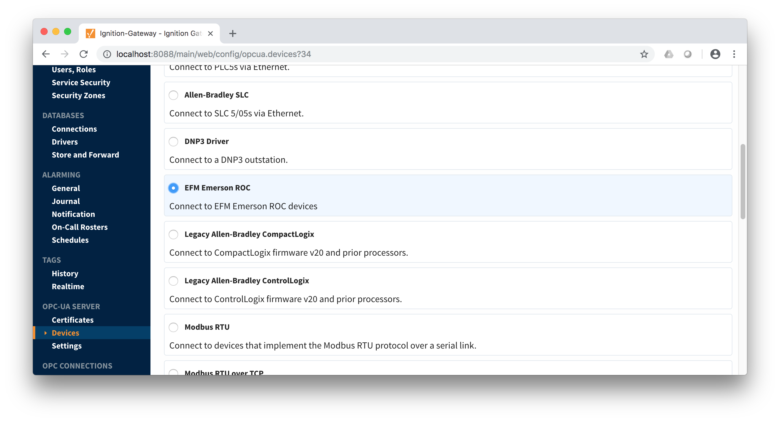 Image Removed
When creating a new device you will see the following.
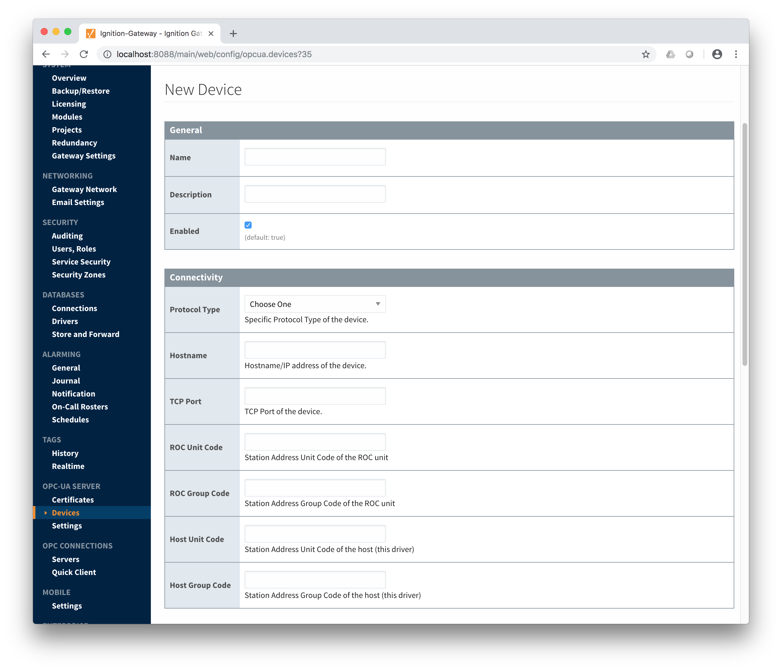 Image Removed
The following describes the parameters that can be set here.
.
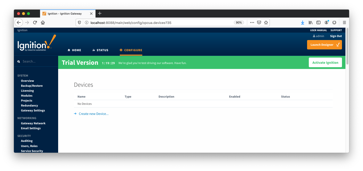 Image AddedAfter clicking the 'Create new Device...' link you will see the following. Select the 'EFM Emerson ROC' and click 'Next' at the bottom of the page.
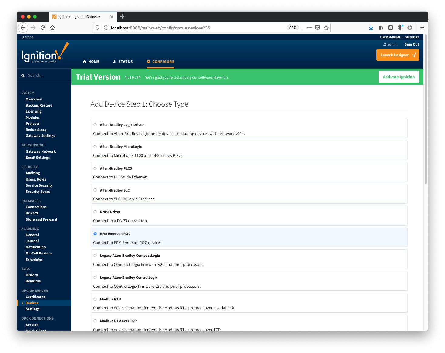 Image AddedWhen creating a new device you will see the following.
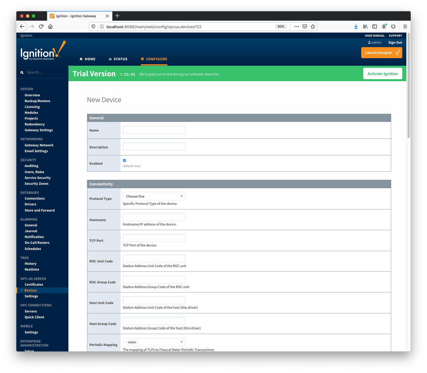 Image AddedThe following describes the parameters that can be set here.
General
Connectivity
- Protocol Type
- Specific Protocol Type of the device
- Hostname
- Hostname or IP address of the device
- TCP Port
- ROC Unit Code
- Station Address Unit Code of the ROC unit
- ROC Group Code
- Station Address Group Code of the ROC unit
- Host Unit Code
- Station Address Unit Code of the host (this driver)
- Host Group Code
- Station Address Group Code of the host (this driver)
- Periodic Mapping
- Select a Periodic History Mapping (see above) if History polling will be enabled
- Configuration Mapping
- Select a Configuration Mapping (see above) if any Configuration, Event, or History polling will be enabled
- Add All TLP Definitions
- If selected, all TLP definitions configured within the module (see above) will be automatically added to this Device configuration. This is a convenient way to easily add TLP definitions to a Device without having to manually add them after the Device has been initially configured. If the module contains one or more TLP definitions that are not compatible with the device being configured, leave this option disabled and configure the TLP Definitions manually after the device has been configured.
Security
- Security Enabled
- Whether security is enabled on the ROC device
- Operator ID
- A three character operator ID
- Password
- Access Level Enabled
- Whether of not the Access Level is enabled for the above operator on the ROC device
- Access Level
- The Access Level to use (0-5) if enabled
Date/Time
- Date Time Offset
- The date time offset of the ROC clock from the Ignition system running this driver in seconds
- Sync ROC RTC
- Sync Expression
Records
- Alarm Scan Rate
- The rate in seconds that alarm records are scanned
- Set to -1 to disable alarm scanning (default)
- Event Scan Rate
- The rate in seconds that event records are scanned
- Set to -1 to disable event scanning (default)
- Minute History Scan Rate
- The rate in seconds that minute history records are scanned
- Set to -1 to disable minute history scanning (default)
- Periodic History Scan Rate
- The rate in seconds that periodic history records are scanned
- Set to -1 to disable periodic history scanning (default)
- Daily History Scan Rate
- The rate in seconds that daily history records are scanned
- Set to -1 to disable daily history scanning (default)
Sparkplug
- Group ID
- An ID representing a logical grouping of Edge Nodes and Devices
- Edge Node ID
- An ID representing an Edge or Network (EoN) Node
- Device ID
- An ID representing a Device
Advanced
- Serial Number
- The serial number to include in Records for uniqueness. Can be manually configured (example: '0001234556') or a TLP can be specified to be read from the device (example: '[15,0,14]').
- History Time Stamp
- If enabled the history time stamp will be at the beginning of the period (leading), otherwise at the end of the period (trailing)
- General
- Name
- The unique name of this device
- Description
- The description of this device
- Enabled
- Whether or not this device is enabled
- Connectivity
- Protocol Type
- Either ROC or ROC Plus depending on the type of device
- Hostname
- The IP address or hostname of the Emerson ROC device
- TCP Port
- The TCP port the Emerson ROC device is listening on
- ROC Unit Code
- The unit code assigned to the ROC device
- ROC Group Code
- The group code assigned to the ROC device
- Host Unit Code
- The host unit code assigned to the Ignition instance
- Host Group Code
- The host group code assigned to the Ignition instance
- Records
- Alarm Scan Rate
- The rate (in seconds) at which the Emerson ROC driver should check for new alarms
- Event Scan Rate
- The rate (in seconds) at which the Emerson ROC driver should check for new events
- Minute History Scan Rate
- The rate (in seconds) at which the Emerson ROC driver should check for new minute history
- Periodic History Scan Rate
- The rate (in seconds) at which the Emerson ROC driver should check for new periodic history
- Daily History Scan Rate
- The rate (in seconds) at which the Emerson ROC driver should check for new daily history
- Sparkplug
- Group ID
- The Sparkplug Group ID which should be used when publishing events, alarms, and history. The Sparkplug Group ID, Edge Node ID, and Device ID must exist in MQTT Transmission in order for records to be published.
- Edge Node ID
- The Sparkplug Edge Node ID which should be used when publishing events, alarms, and history. The Sparkplug Group ID, Edge Node ID, and Device ID must exist in MQTT Transmission in order for records to be published.
- Device IDThe Sparkplug Device ID which should be used when publishing events, alarms, and history. The Sparkplug Group ID, Edge Node ID, and Device ID must exist in MQTT Transmission in order for records to be published.
Once the device is created, you should see it is listed in the devices section with a status of 'Not Configured' as shown below. The next sections will show the rest of the configuration that will complete the setup.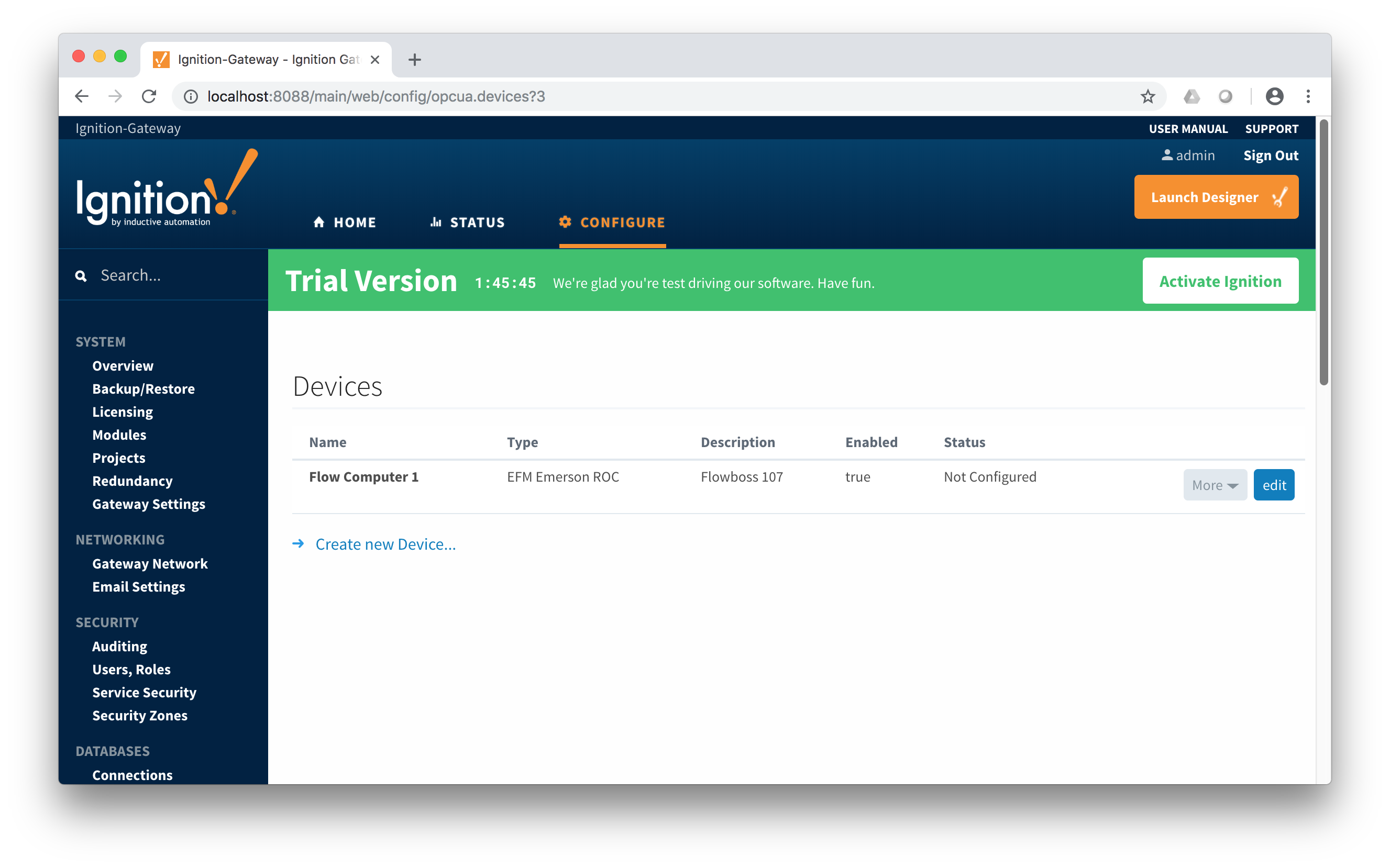 Image Removed
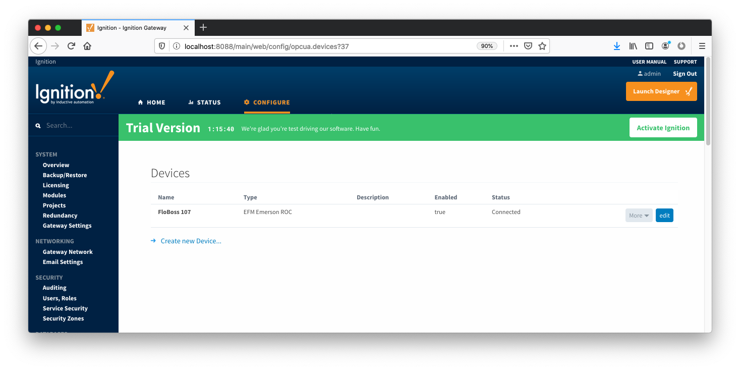 Image AddedSpecifying TLP Definitions for a Device
With the device now established the specific global TLP templates that are appropriate for this device must be associated with it. Do so by clicking the 'More' drop-down button and selecting 'TLP Definitions' as shown below.
 Image Removed
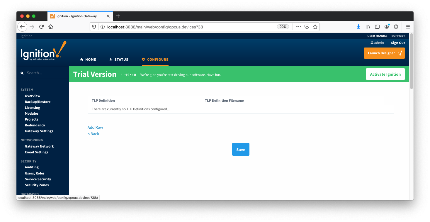 Image AddedYou should now see an empty list of TLP definitions associated with this specific device(unless you used the "Add All TLP Definitions" setting). Click the 'Add Row' link that is shown below.
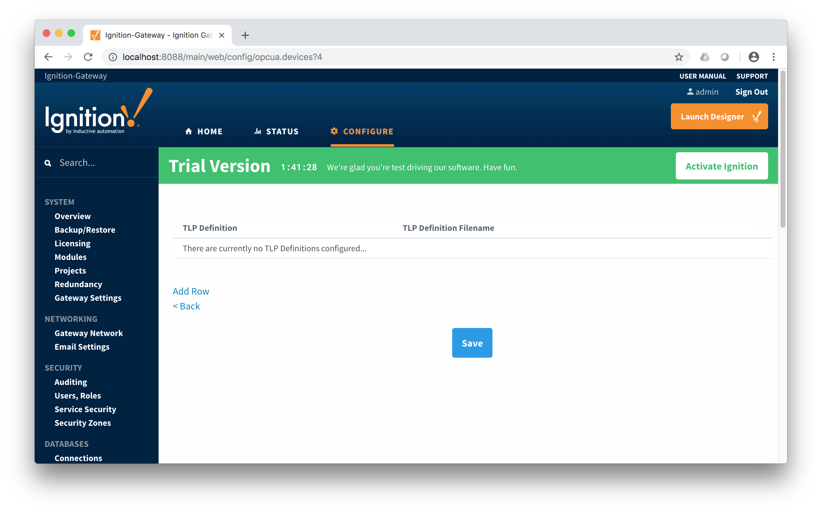 Image Removed
This will show a new TLP definition with a select box to allow you to select which global TLP definition you want to associate with this device. Add as many as are appropriate for your device as shown below.
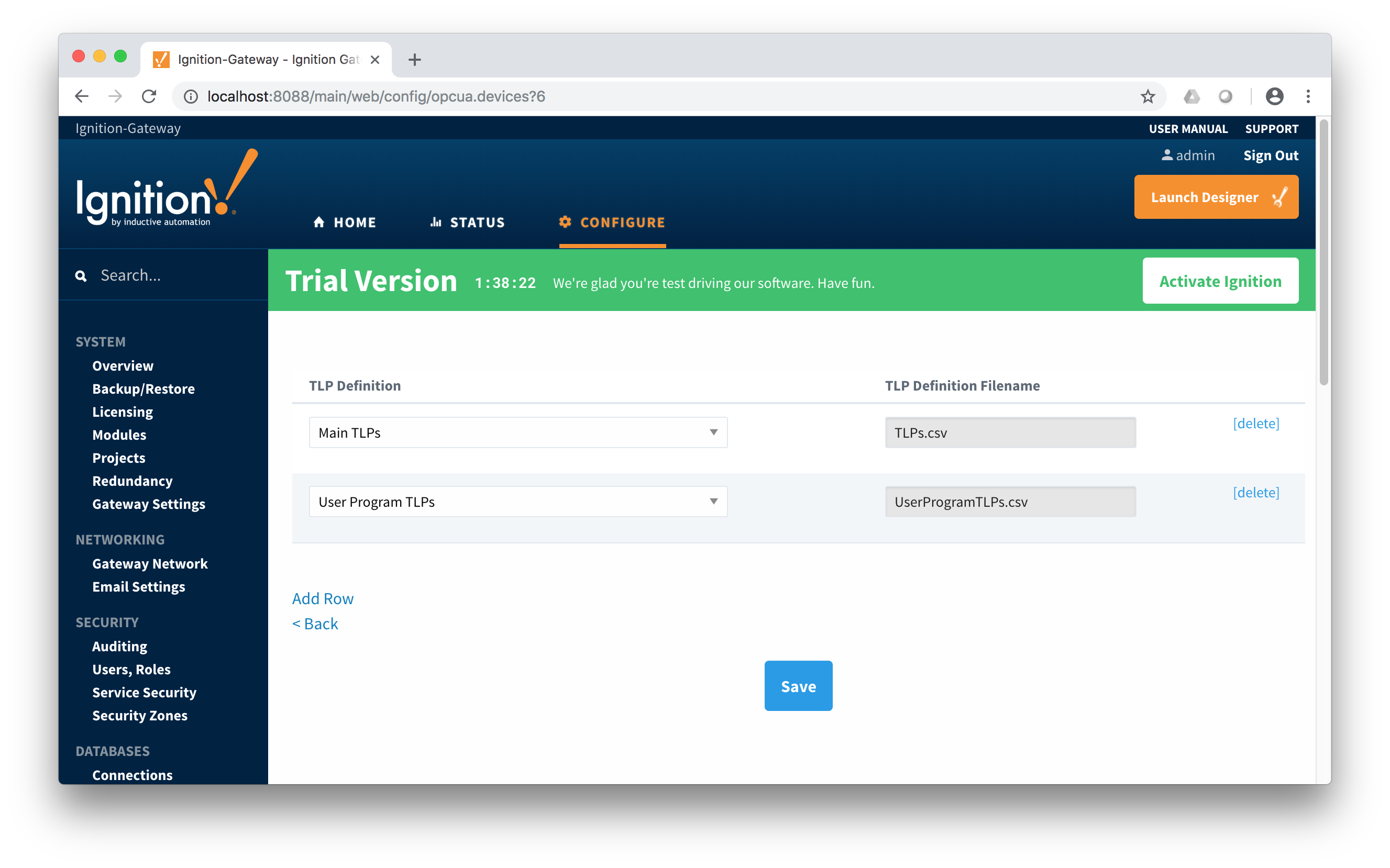 Image Removed
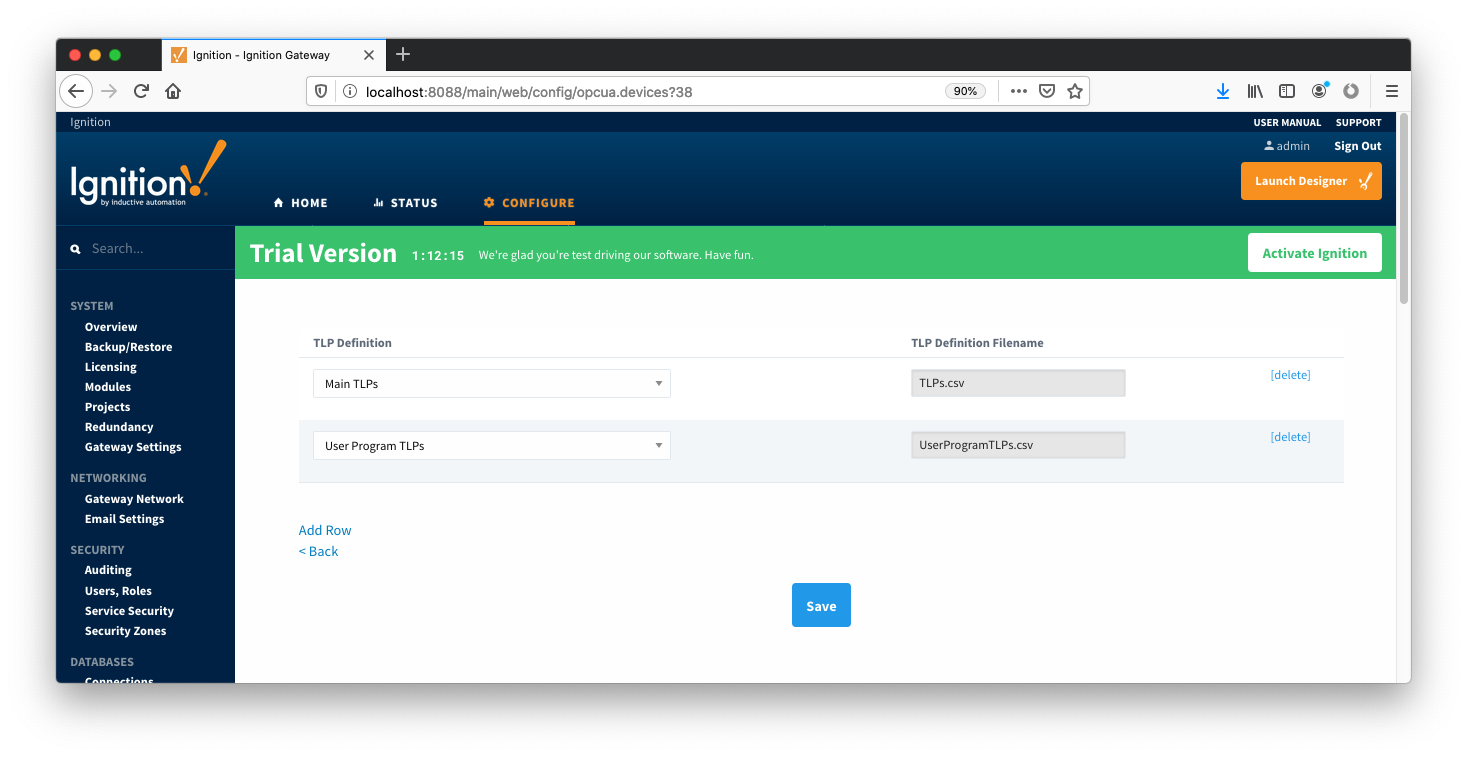 Image Added
When complete, save the list and you will be taken back to the Devices list.
...
With the TLP definitions now defined for this device we can create some TLP templates to allow creation of TLP poll groups. You should also note at this point that the Status shows 'Connected' for the device. To create a TLP template, click on the 'More' drop-down menu and select 'TLP Templates' as shown below.
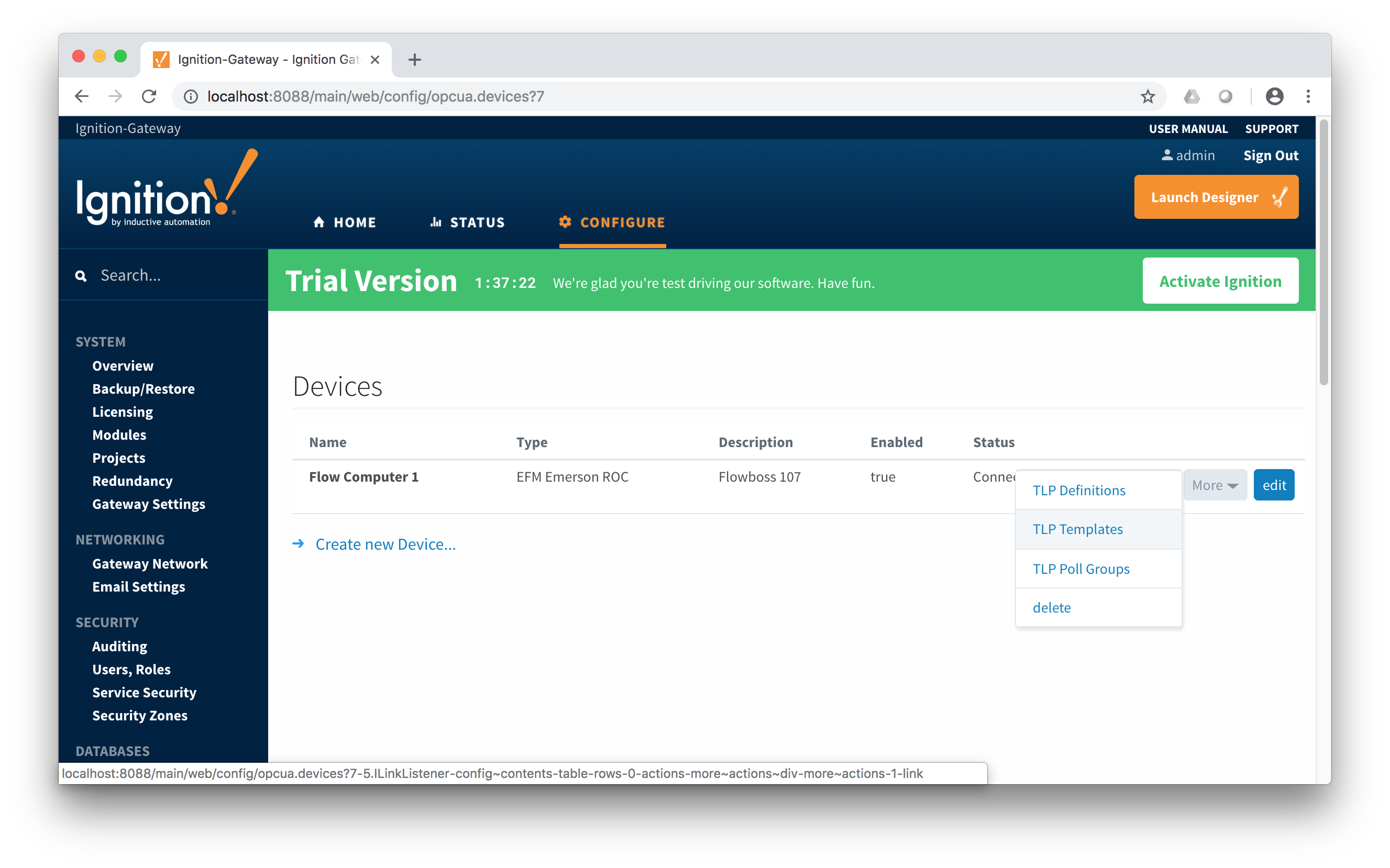 Image Removed
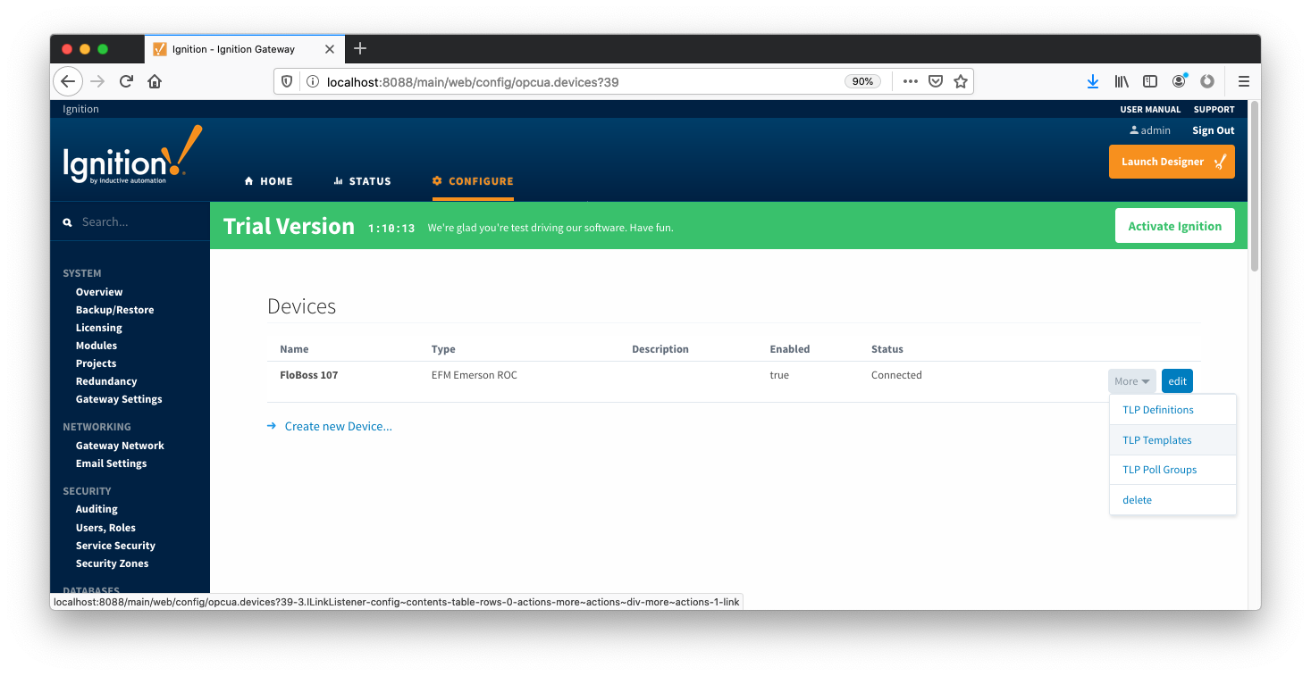 Image AddedTo add a TLP template, click the 'Add Row' link shown below.
 Image Removed
 Image AddedAt this point you can give the new TLP template a name that makes sense. Then click the 'Edit TLP Template Contents' link next to the name field shown below.
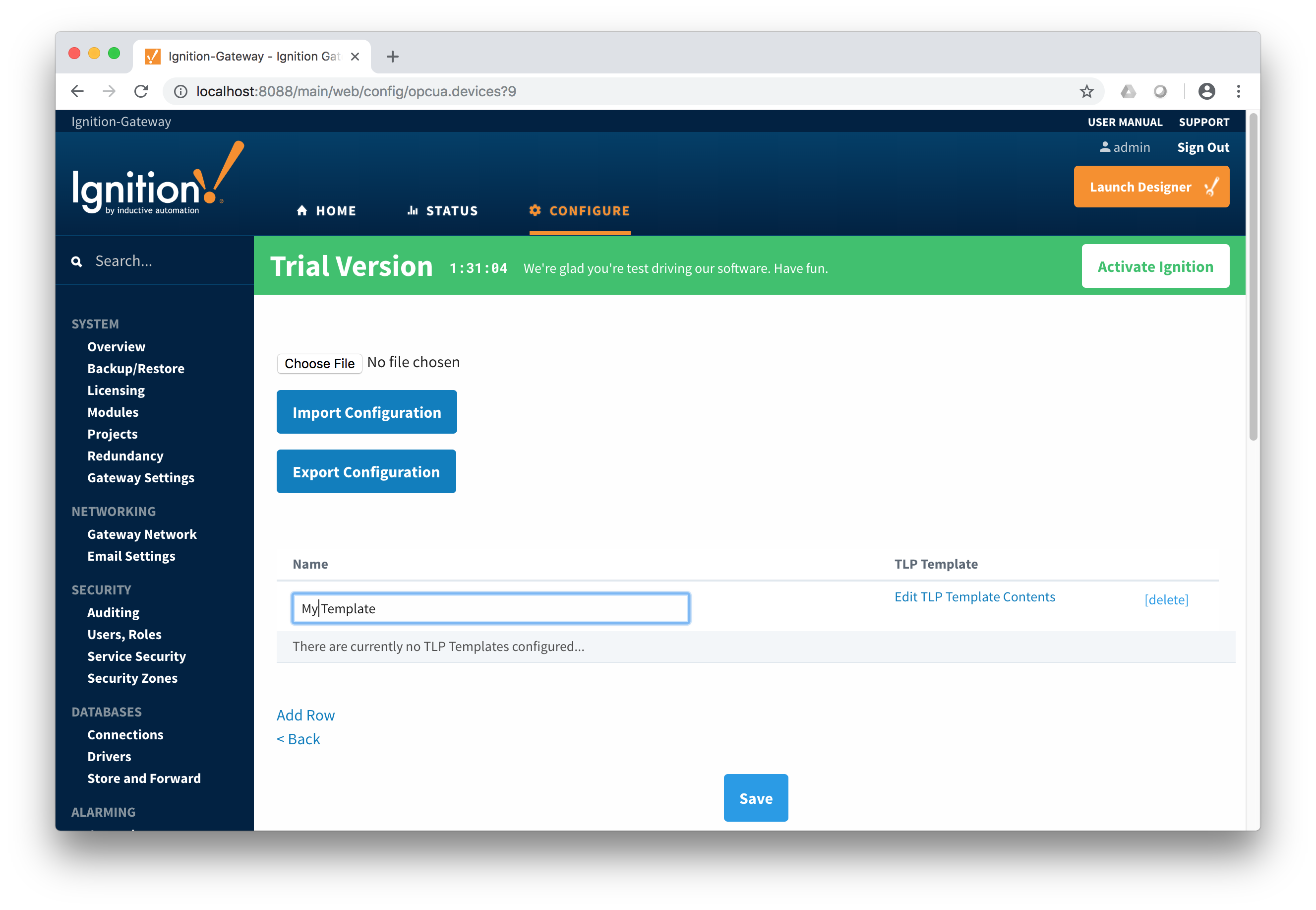 Image Removed
 Image AddedAt this point you can begin adding new TLPs by clicking the 'Add Row' link shown below.
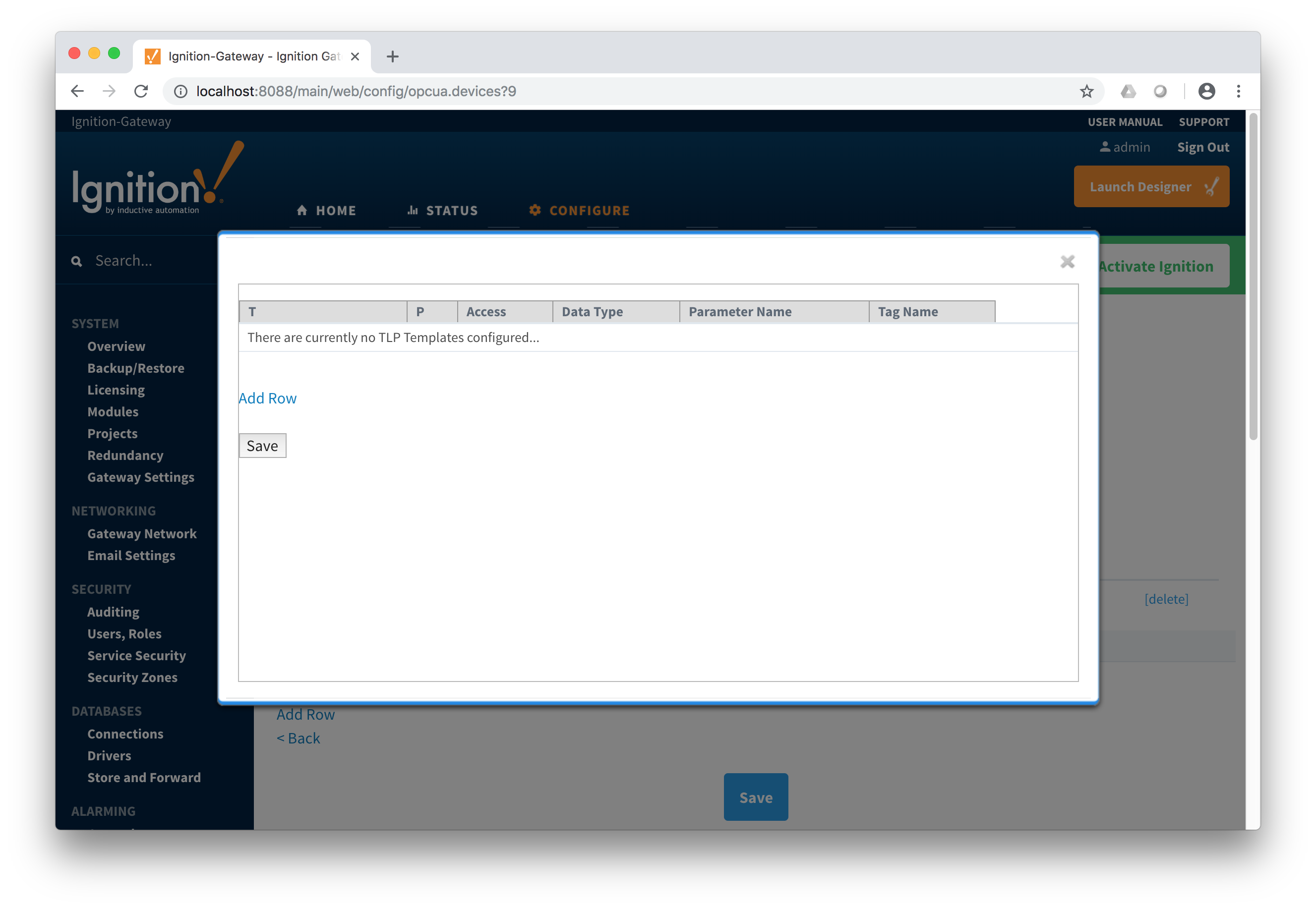 Image Removed
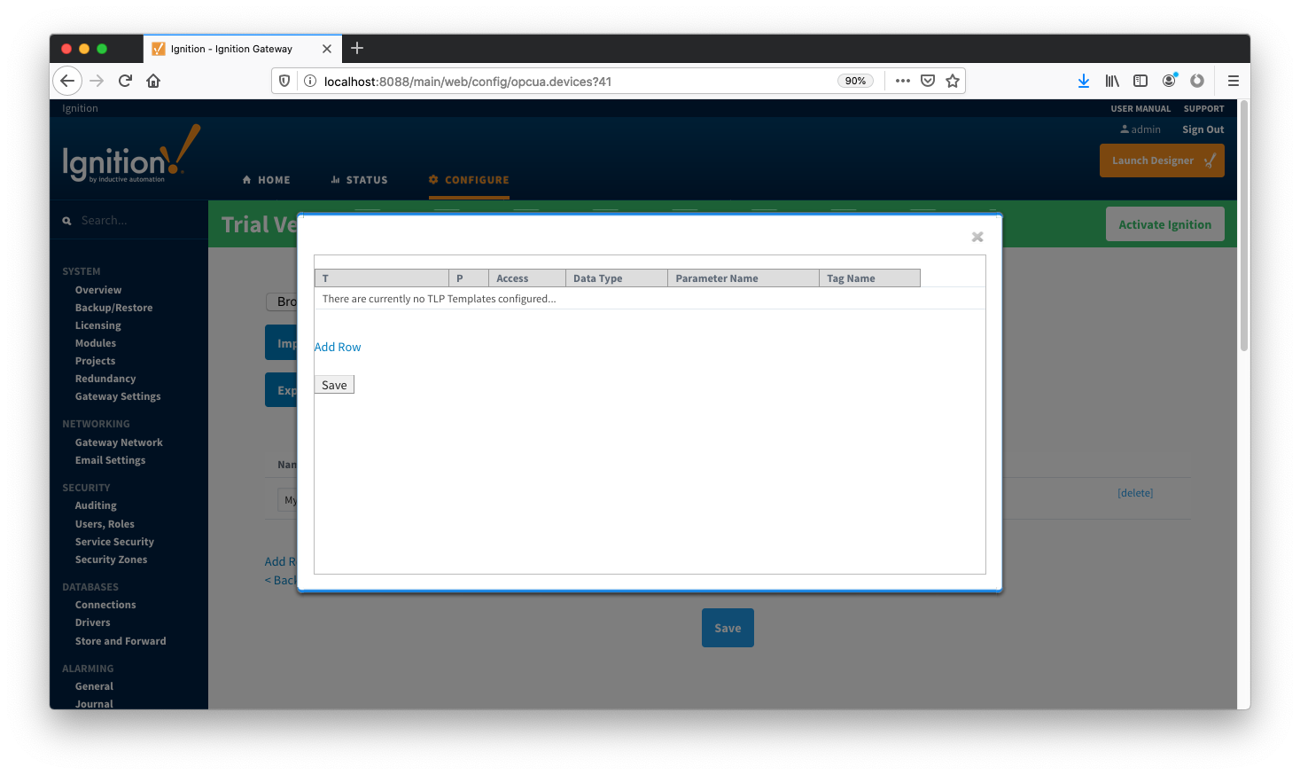 Image AddedThe TLPs available to be added are based on the TLP definitions that have been made available to this specific device. Add TLPs that make sense to be grouped together in a logical group. When complete you should see something similar to what is shown below. Click the 'Save' button.
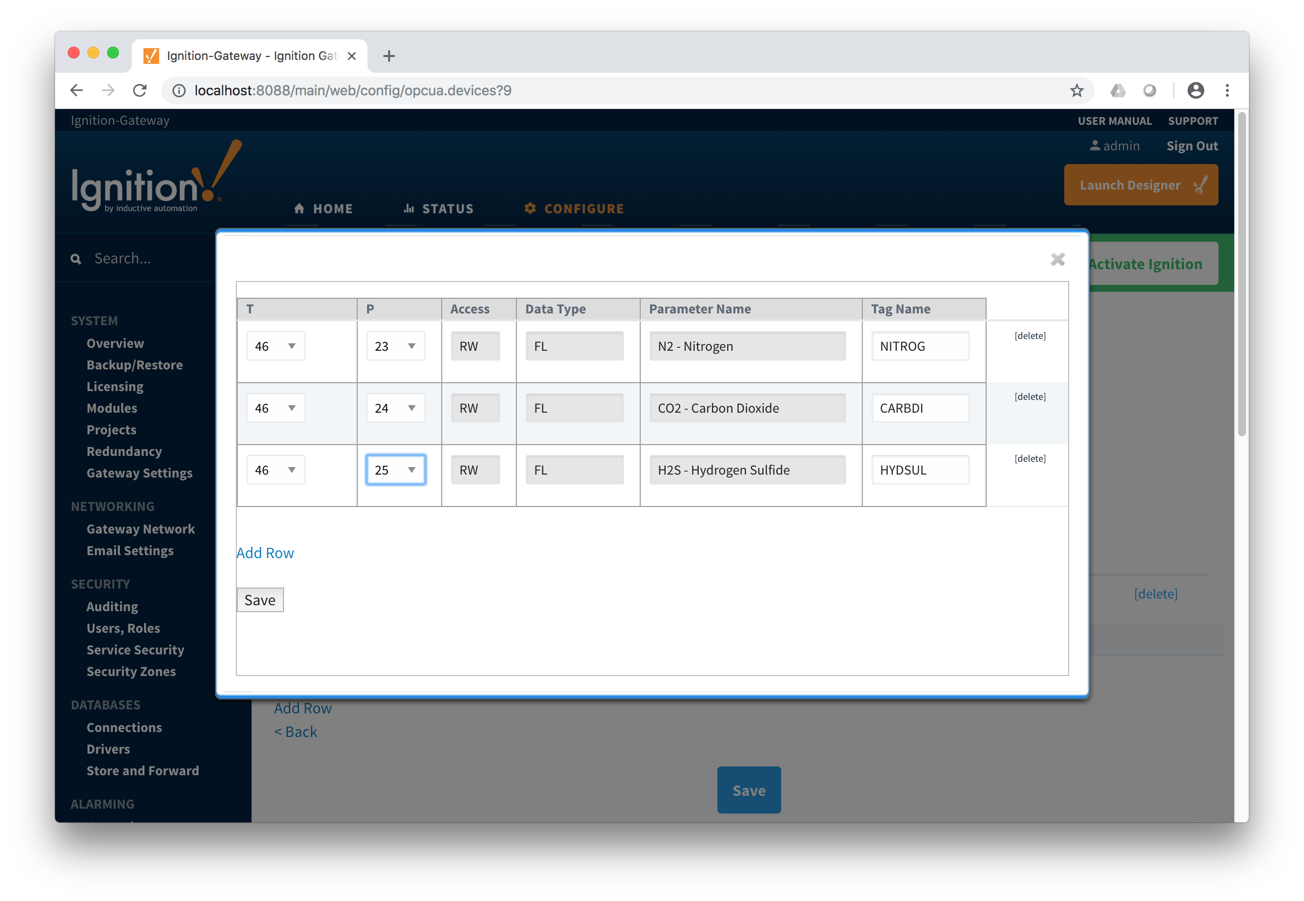 Image Removed
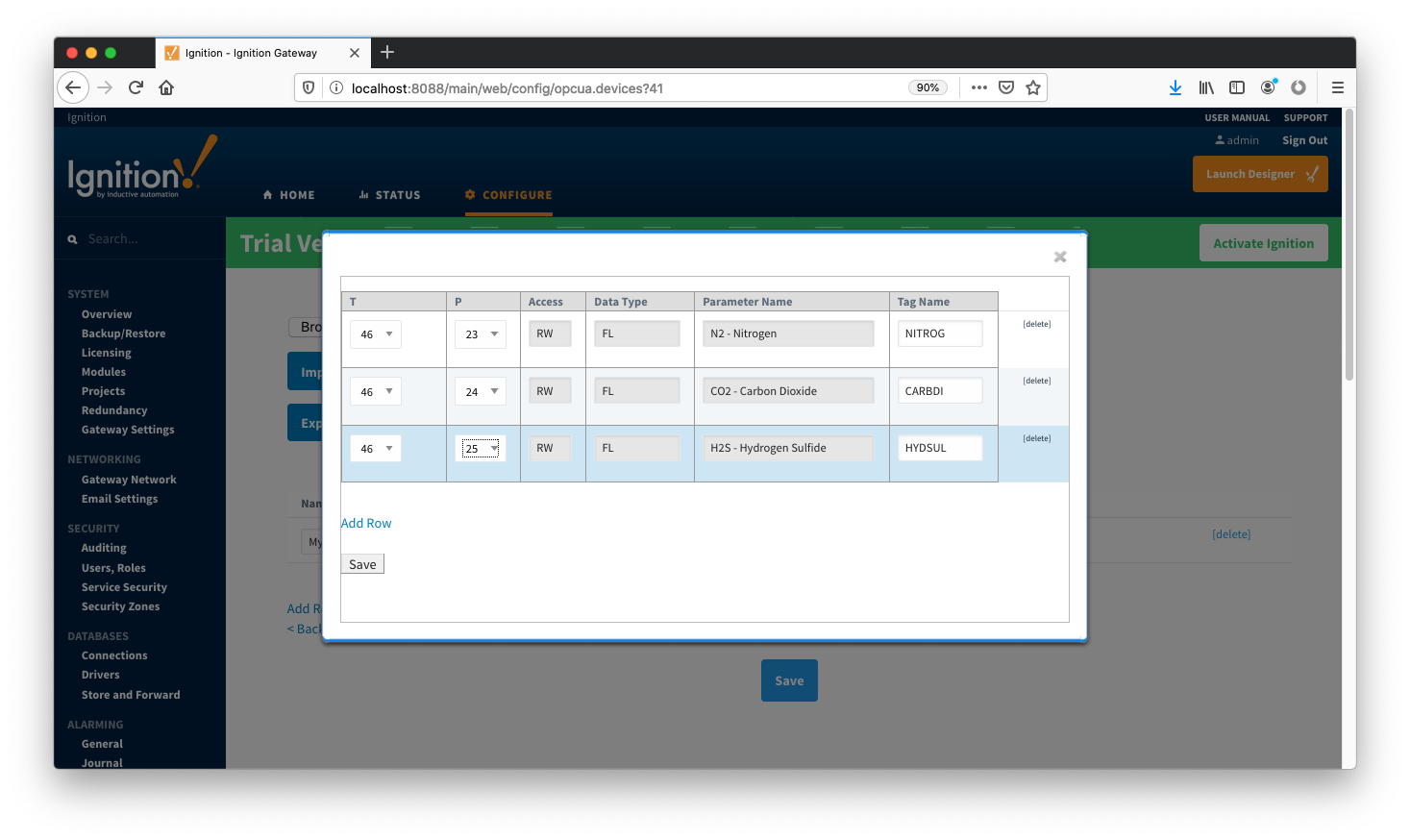 Image Added
Note there are six fields available for each row of which only three can be modified. These are:
...
Add as many templates as you'd like, then click the 'Save' button at the bottom of the page shown below.
 Image Added
 Image RemovedCreating TLP Poll Groups for a Device
With TLP templates already defined you can now create TLP poll groups which will poll a group of TLPs via a TLP template at a specific logical number at a specified rate. Do so by selecting 'TLP Poll Groups' via the 'More' drop-down as shown below.
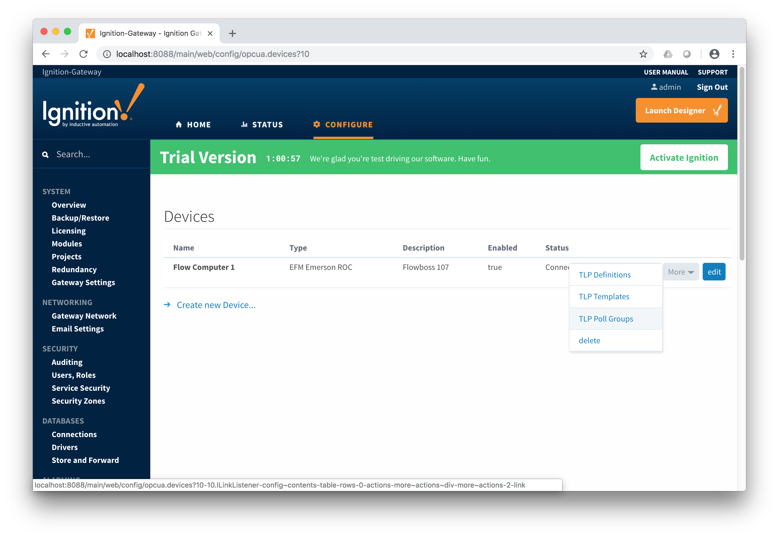 Image Removed
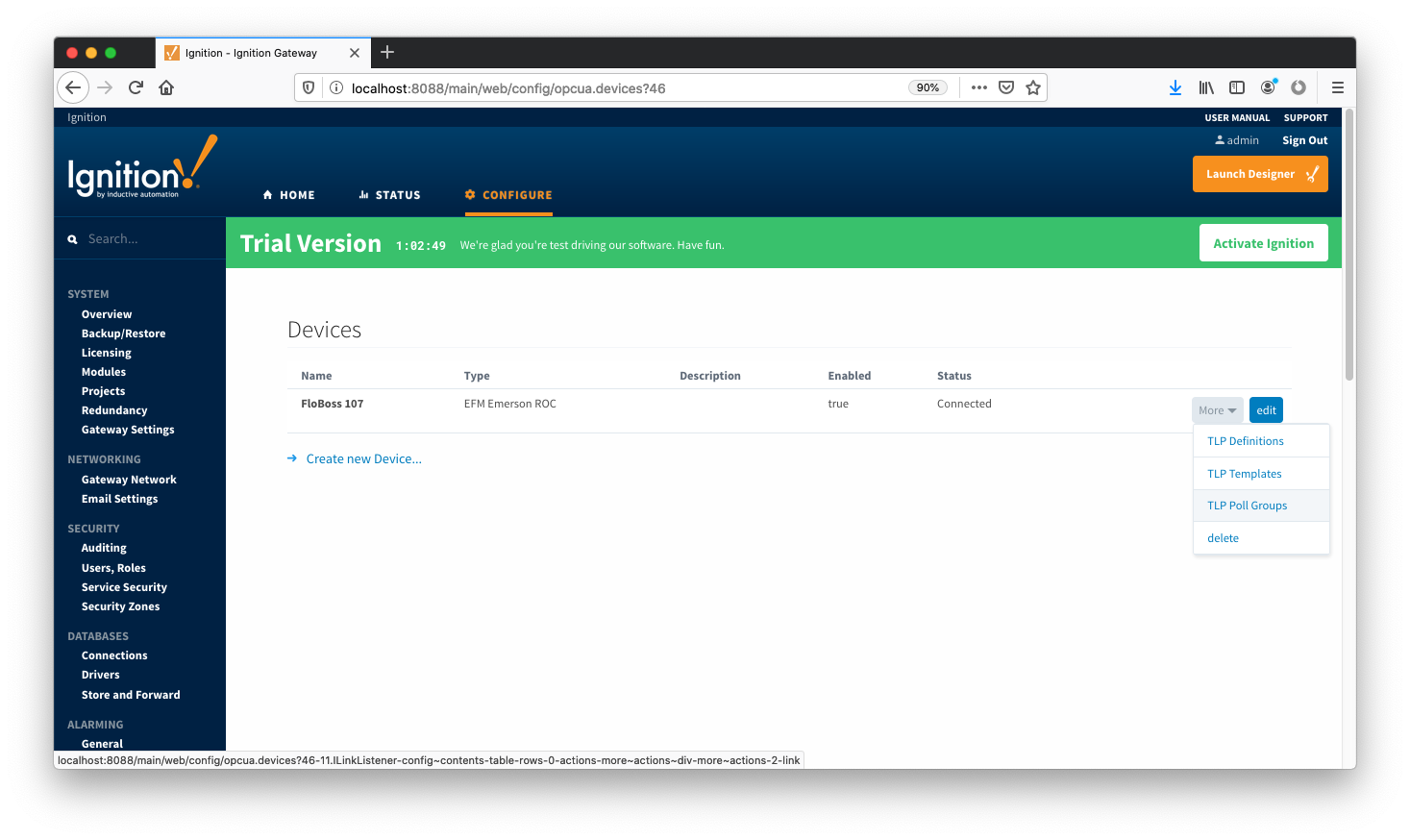 Image AddedTo add a TLP poll group, click the 'Add Row' link shown below.
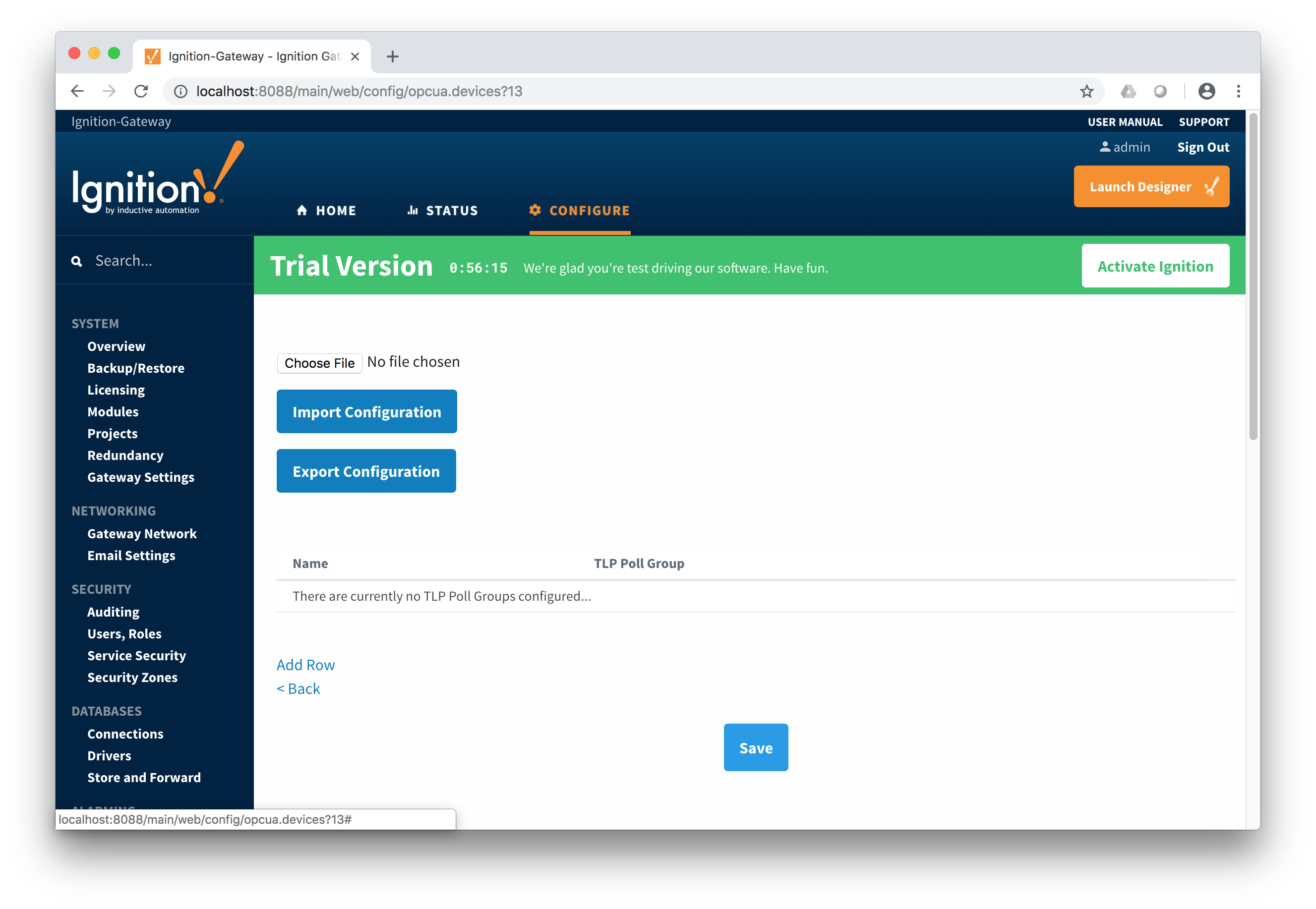 Image Removed
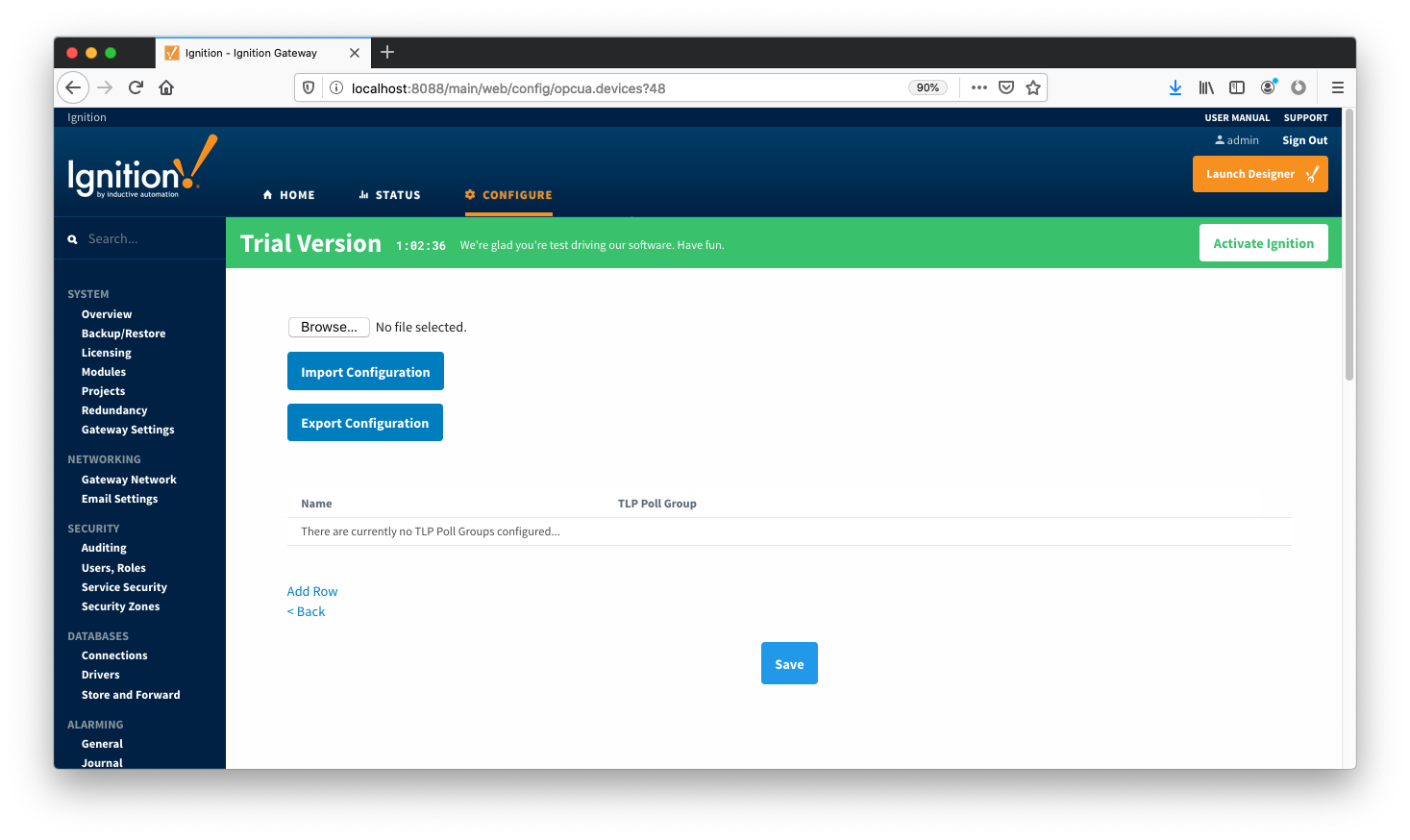 Image AddedNow you can give the new TLP poll group a name that makes sense. Then click the 'Edit TLP Poll Group Contents' link next to the name field shown below.
 Image Removed
 Image AddedAt this point you can create a poll group using one or more TLP templates as shown below. The parameters that must be set here are:
...
When complete, click the 'Save' button to save the TLP poll group.
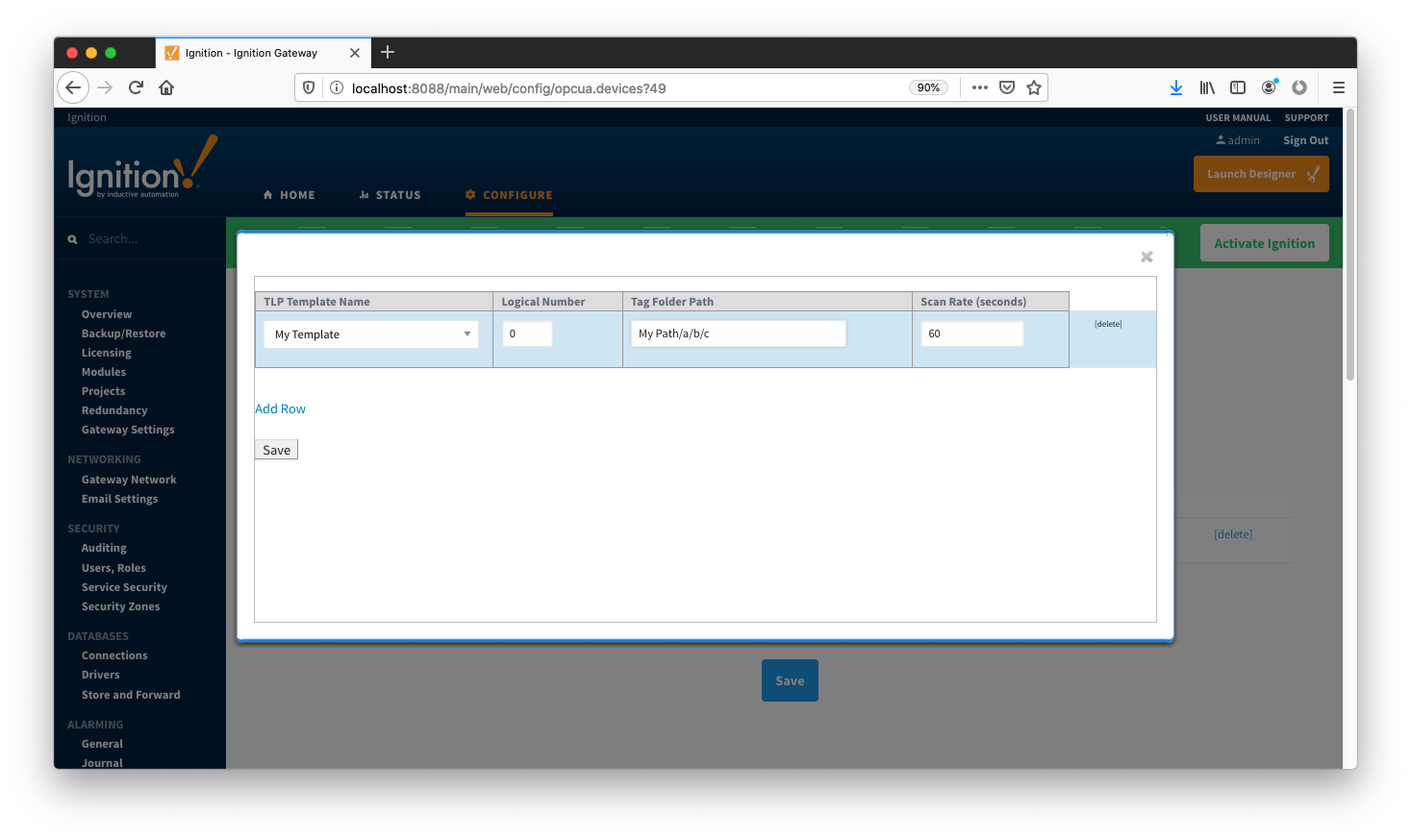 Image Added
 Image RemovedCreate as many TLP poll groups as you'd like. Once complete, click the 'Save' button at the bottom of the page below.
 Image Removed
 Image Added
Viewing Device TLP Data
...