...
Once you save the configuration for the Modbus TCP connection and everything is setup properly on the MGate you should see the “Status” of the connection change to “Connected”.

********************************************************************************************
How did we get from this connected status to seeing the CLICK devices in Designer?
...
Setting up the Ignition Tags in Designer
Configuring Modbus Registers to Use Modbus TCP with Modbus RTU Unit Addresses
In Designer, create a tag path and add OPC tags.
When you start to configure Ignition tags that want pull Modbus register information from any of the Modbus RTU devices connected to the MGate unit, you will need to specify the Modbus Address in the OPC tag path.
In our example, we have three (3) CLICK PLCs on the RS-485 2-wire serial network connected to the MGate. The Modbus register values are in the Ignition folders CLICK 01, CLICK 02, and CLICK 03.
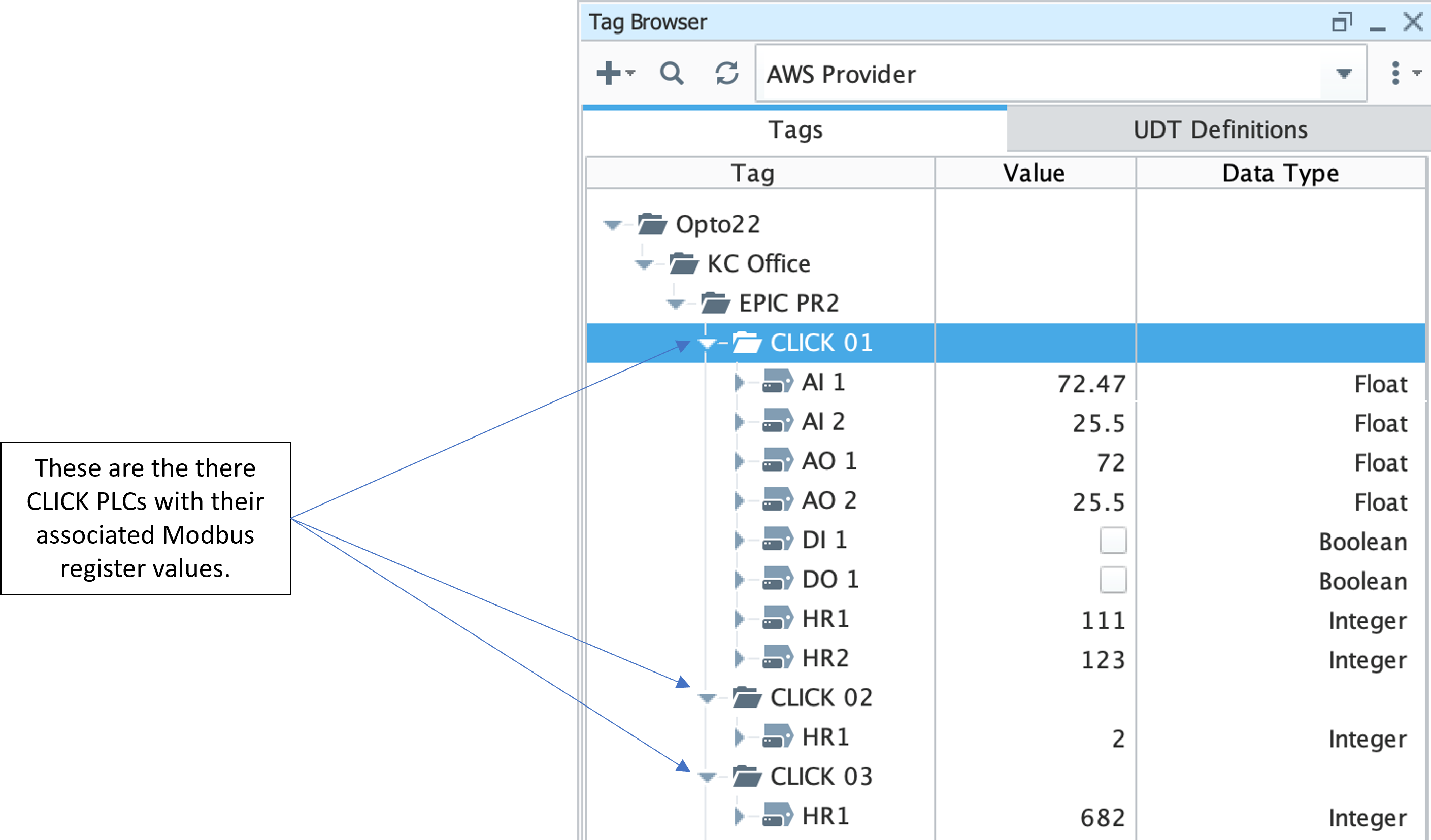 Image Removed
Lets review the various datatypes available and how they are mapped RTU Address, Modbus Data Type and Modbus Register Address by appending to the OPC Server Path in the OPC Item Path configuration..
The format is [OPCServerPath]X.YYY.ZZZZZ where:
X = Modbus RTI Address
YYY = Modbus Datatype
ZZZZZ = Modbus Register Address Image Removed
| Tip |
|---|
| Reference the Modbus Addressing Inductive Automation document for details on the correct designator to use for the datatype |
32-bit Float
Double click on the AI 1 tag under CLICK 01 to open the properties and look at the OPC Item Path configuration:
 Image Removed
Here we can see that Analog Input #1 on the CLICK 01 PLC (tag AI 1) is mapped to Modbus Holding Register address 28,674. Also note that the Analog Input is a 32-bit Float data type. In this use case, the OPC Item Path must include the associated Modbus Slave Address for the target PLC.
 Image Removed
Discrete Input
...
In our example, with the OPC UA Server Path as ns=1;s=[Click PLC RS485 Network]
- The OPC Item Path for an analog input of type Float with a Modbus Holding Register address of 28,674 from Modbus RTU Address 1 would be
- ns=1;s=[Click PLC RS485 Network]1.HRF28674
- The OPC Item Path for a digital input of type Boolean with a Modbus Discrete Input Register address of 1 from Modbus RTU Address 1 would be
- ns=1;s=[Click PLC RS485 Network]1.DI1
- The OPC Item Path for an analog input of type Integer with a Modbus Holding Register address of 1 from Modbus RTU Address 2 would be
- ns=1;s=[Click PLC RS485 Network]2.HR1
In our example, we have three (3) CLICK PLCs on the RS-485 2-wire serial network connected to the MGate. The Modbus register values are in the Ignition folders CLICK 01, CLICK 02, and CLICK 03.
Image Added