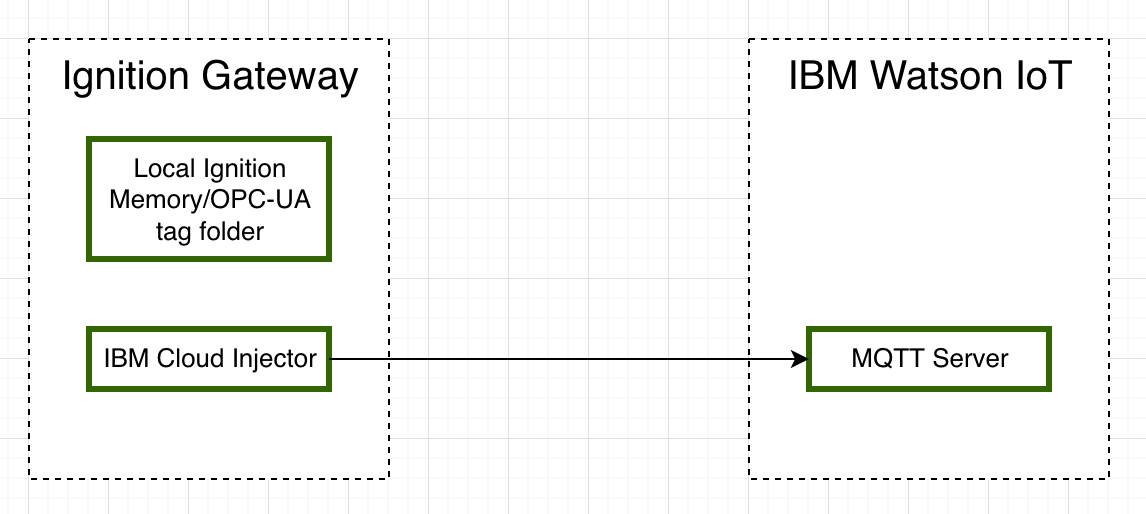
This tutorial will provide step-by-step instructions for the following:
Upon completion of this module you will have an Ignition Gateway connected and publishing live Tag data to the IBM Watson IoT Platform.

Ignition is an Industrial Application Platform that can be used to create SCADA and HMI solutions. A fully functional Ignition system can be downloaded and run in trial mode. Using Ignition as a tool in this way, we can install the Sparkplug MQTT Modules and observe everything working.
Go to the Inductive Automation download page and download the desired version (select version from the 'Ignition Version' dropdown) of the Ignition installer for Windows, Linux or MacOS; https://inductiveautomation.com/downloads/archive
Once the Ignition installer has been downloaded, follow the instructions provided by Inductive Automation to install and startup Ignition.
Go to the Inductive Automation download page again and scroll down to the Third Party modules section. Find the Cirrus Link modules section and download the IBM Cloud Injector Module.
https://inductiveautomation.com/downloads/archive. The download links should look similar to what is shown below.
Once you have Ignition installed and running, and the IBM Cloud Injector module downloaded, browse to the Ignition Gateway console (e.g. http://localhost:8088). Login using the default credentials of admin/password. Click on Configuration tab and then click on the Modules tab on the left side of the page. Scroll to the bottom of the Modules section and click on the Download/Upgrade modules button. When prompted, select the IBM Cloud Injector module from the file browser and install it. When complete, the Ignition Gateway Web UI module section should look similar to what is shown below:
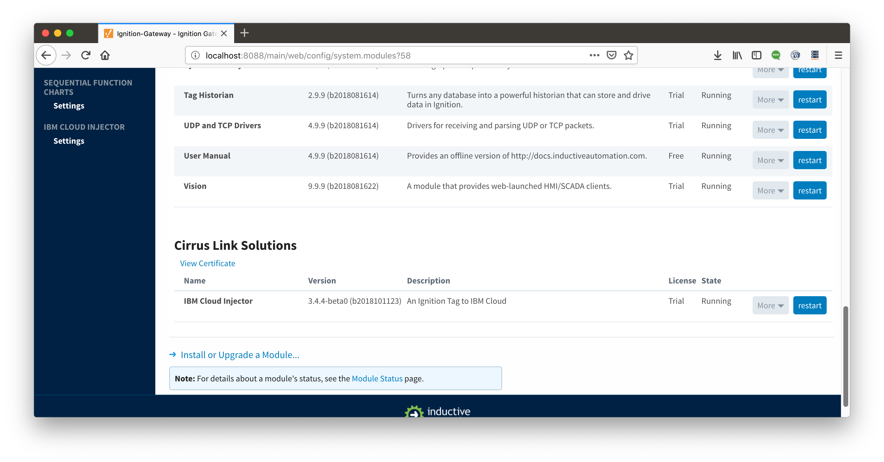
Select the "IBM CLOUD INJECTOR" → "Settings" link on the lower left of the page to navigate to the IBM Cloud Injector Module's configuration page. A detailed explanation of each configuration tab can be found here. For this tutorial, we will only be adding a new IBM Cloud MQTT Setting.
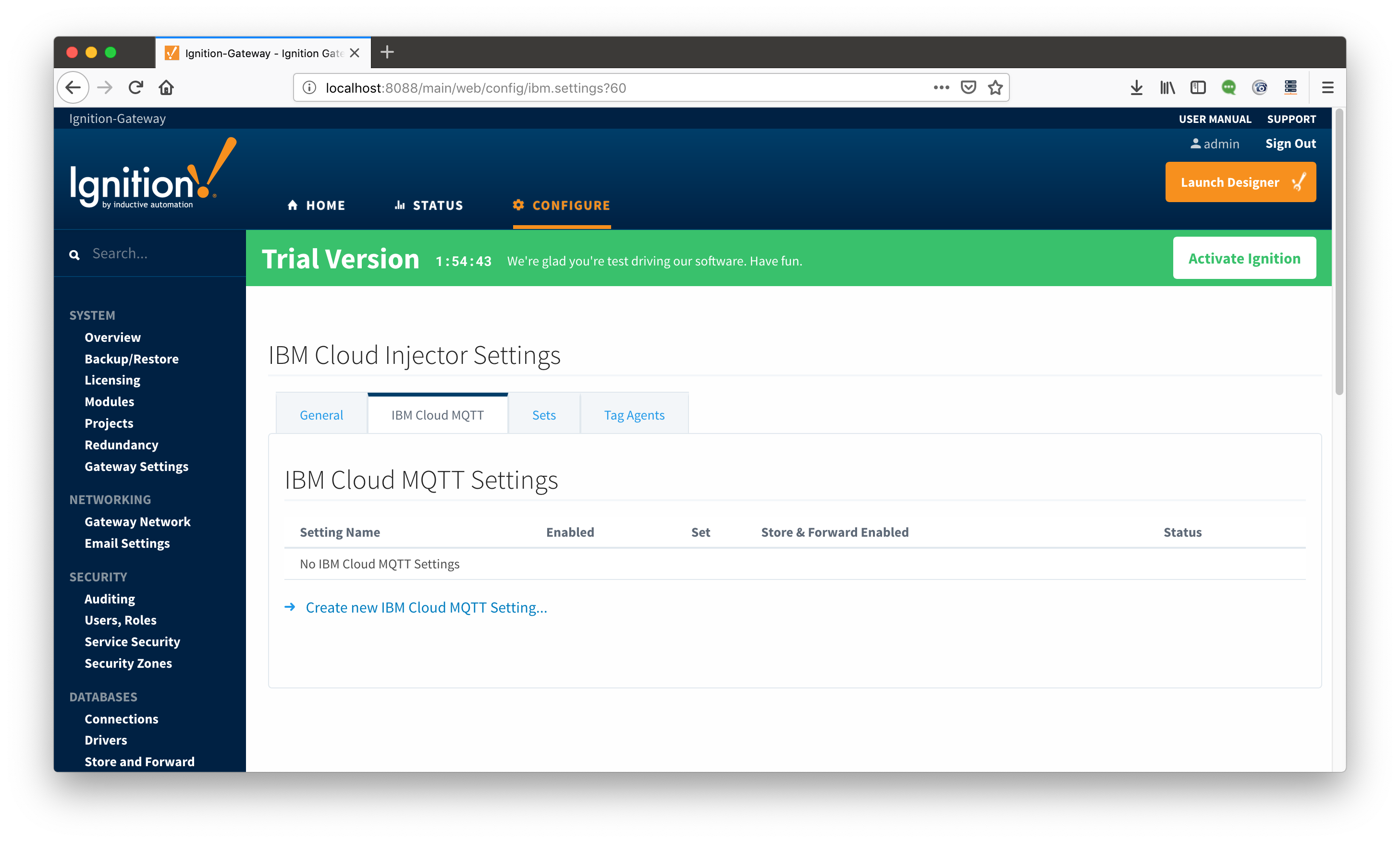
Click on the "Create new IBM Cloud MQTT Setting..." link to bring up the following configuration form:
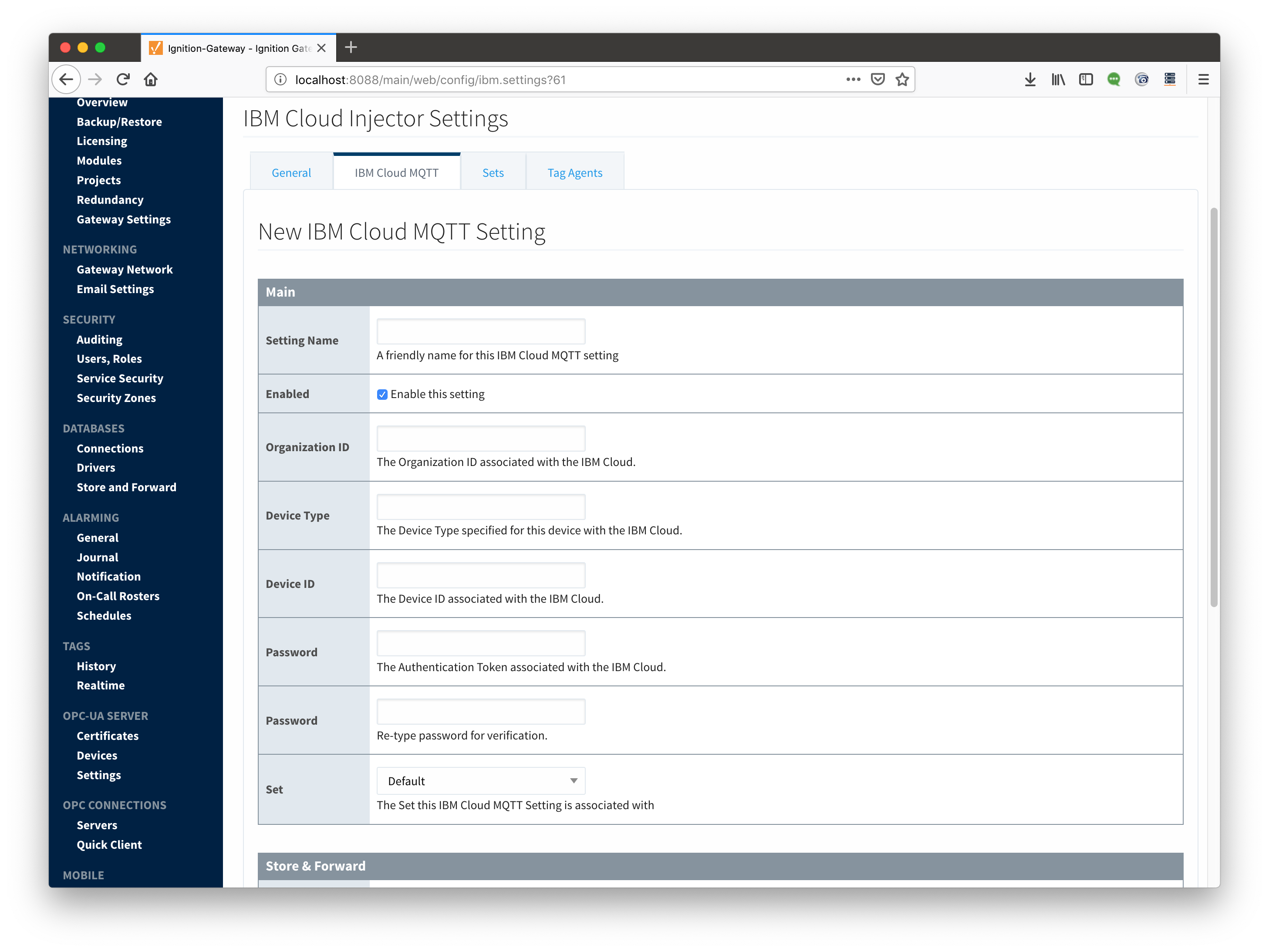
Set the parameters as follows:
Everything in the 'Store & Forward' and 'Advanced' settings can be left default. Click on "Create New IBM Cloud MQTT Setting" to finish creating the new configuration setting.
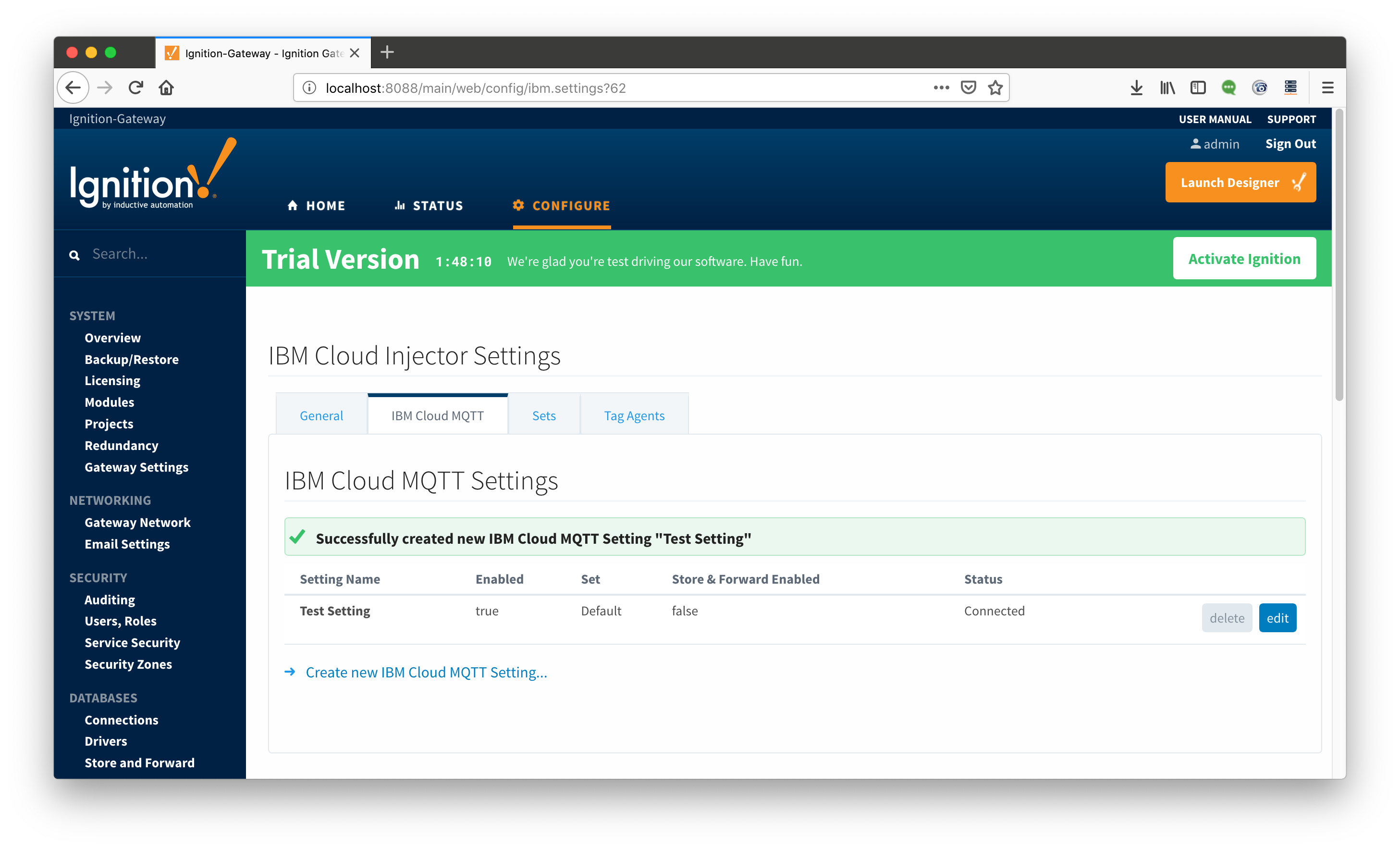
Now the IBM Cloud Injector module is connected to the MQTT server in IBM Cloud and ready to push Tag data.
If you click on the "Tag Agents" tab you will see that out-of-the-box the IBM Cloud Injector module will have one default Tag Agent defined. For this tutorial we will not need to make any configuration changes to the Tag Agents.
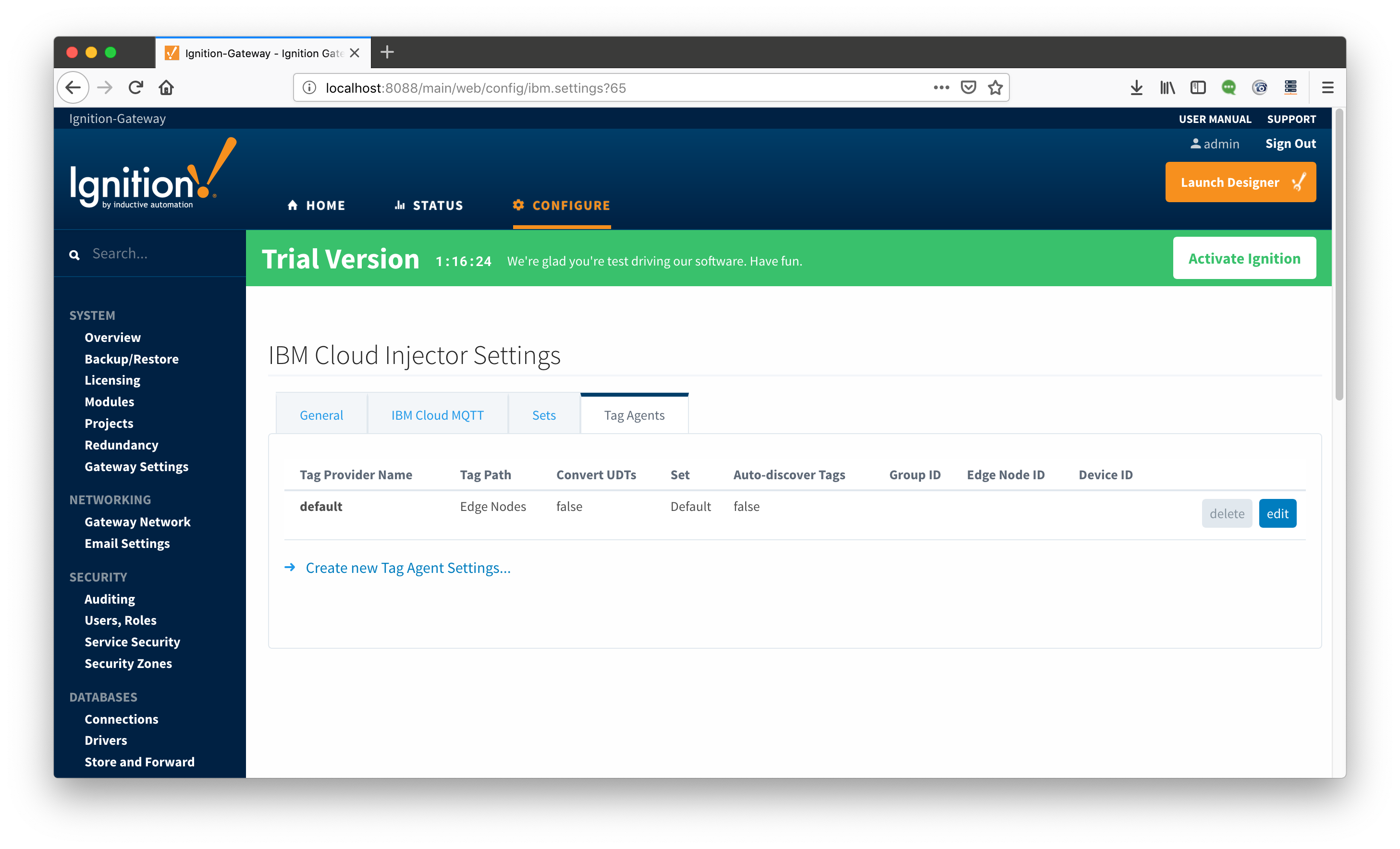
The Default Tag Agent will monitor tags that are in the "Edge Nodes" folder of the "default" Tag Provider. In the next step we go into more detail about the tags in this folder.
With Ignition running and the IBM Cloud Injector module loaded now we can open the Ignition Designer to create/observe the initial Tag structure. Regardless of the OS Ignition is running on, there is a “Launch Designer” button on the Ignition Gateway Console. From here you can launch your Designer on any machine. This is shown below. The default credentials for the designer are the same as the Gateway Console, admin/password. Once you have logged into the Designer enter a new project name and open the project. The project name that we used for this tutorial is simply called “Tutorial1”.
After Designer opens, you will see the default Designer screen as shown below.
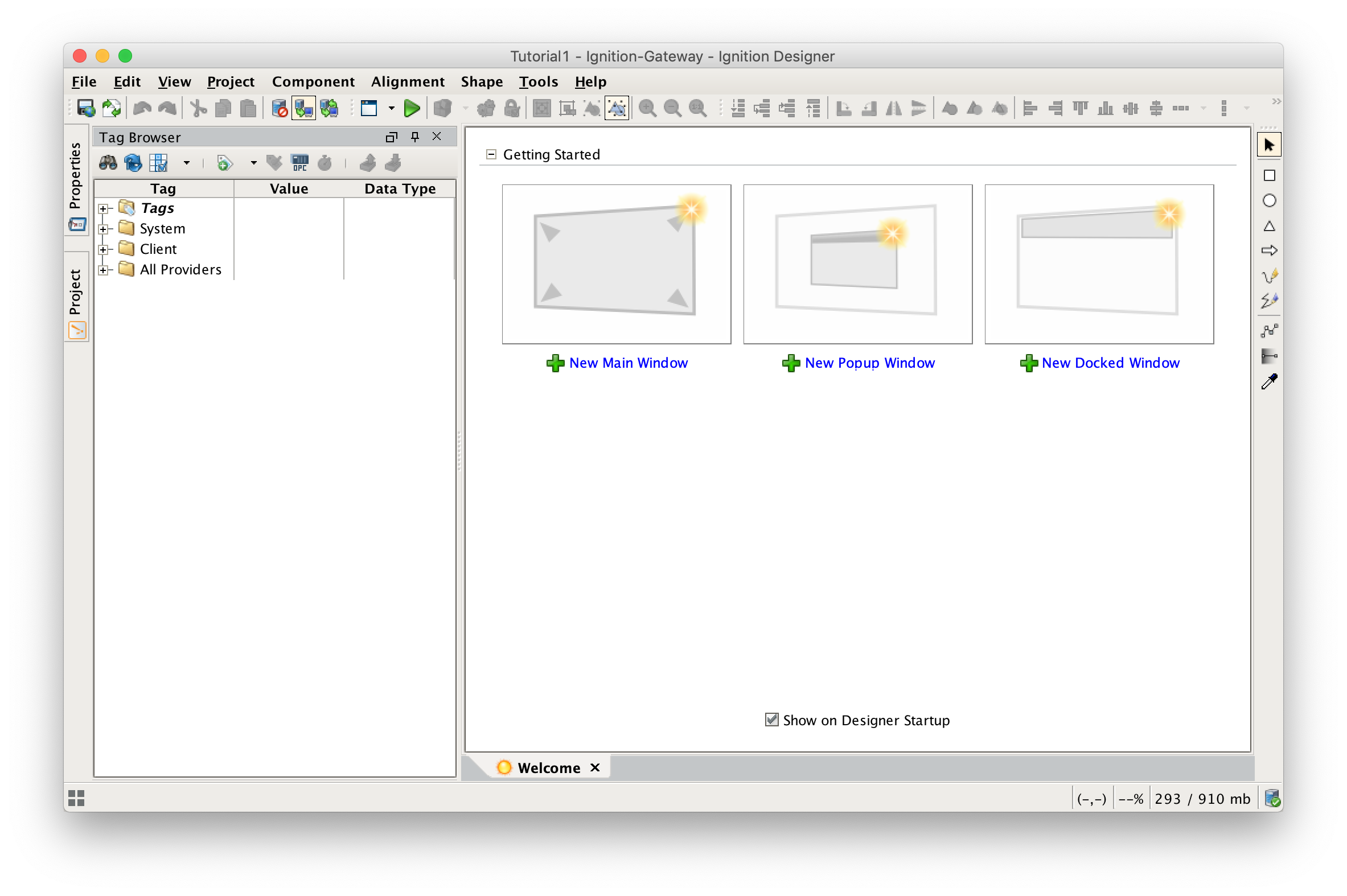
Next, we need to create a folder structure where we will create a virtual Edge device and some tags to be published by the IBM Cloud Injector module. When the IBM Cloud Injector module is installed in Ignition, a folder is automatically created in the Ignition tag structure with the following path:

For this tutorial, right click on the Edge Nodes folder and create a new folder called Tutorial Group. Then right click on the Tutorial Group folder and create another new folder called Tutorial Edge Node. Finally, right click on the Tutorial Edge Node folder and create another new folder called Tutorial Device. This folder structure creates the same hierarchy that is described in the Sparkplug B specification of Group ID, Edge ID, and Device ID.
With this folder structure in place, now we can create some memory tags of various data types to publish. Right click on the Tutorial Device folder and select ’New Tag’/’Memory Tag’. In the tag editor change the Name of the tag to “Boolean001”, and change the Data Type to Boolean. Follow this same procedure for new memory tags called “Integer001” of type Integer, “Float001” of type Float, and “String001” of type String. The resulting folder structure should look as follows.
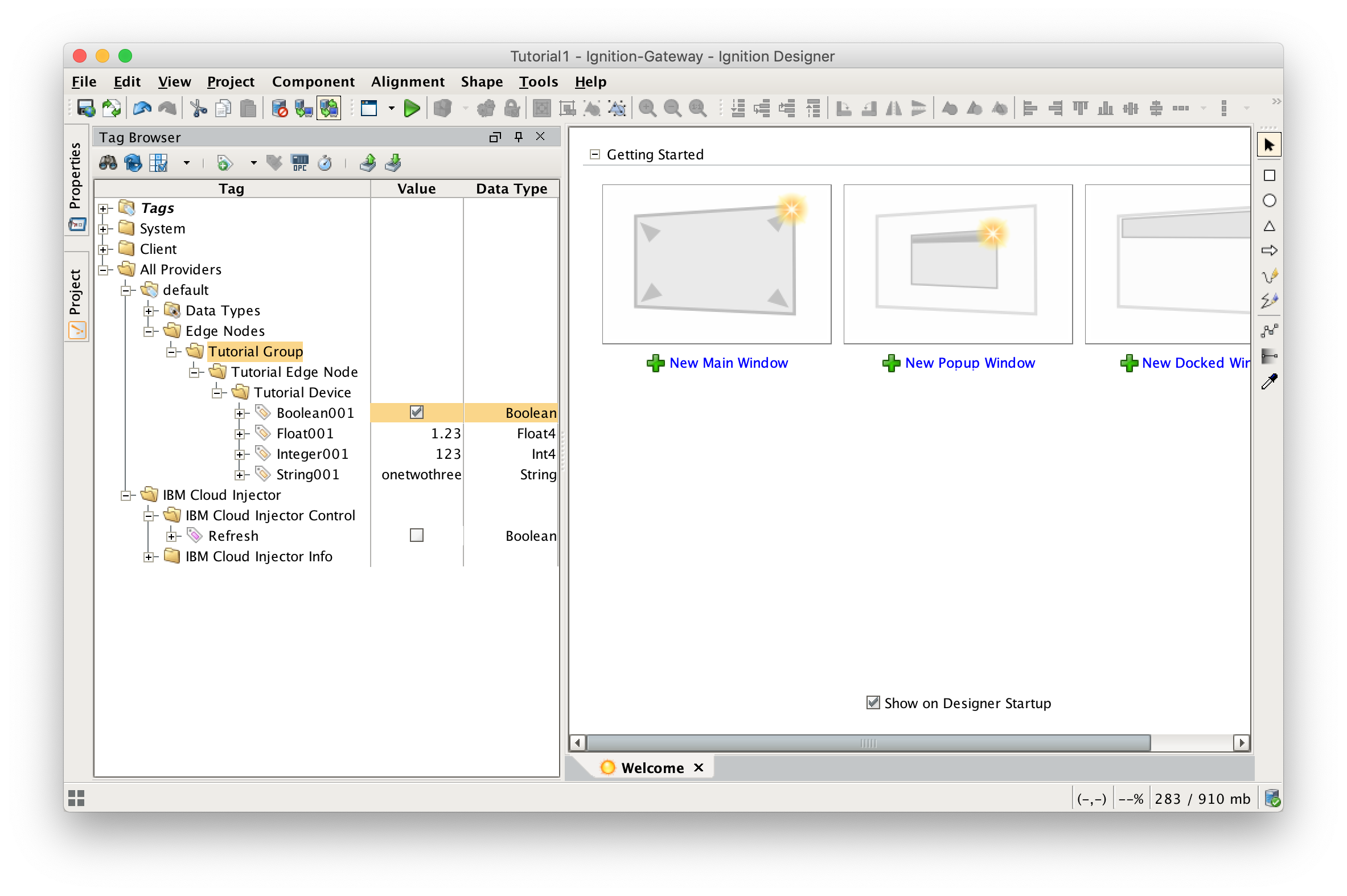
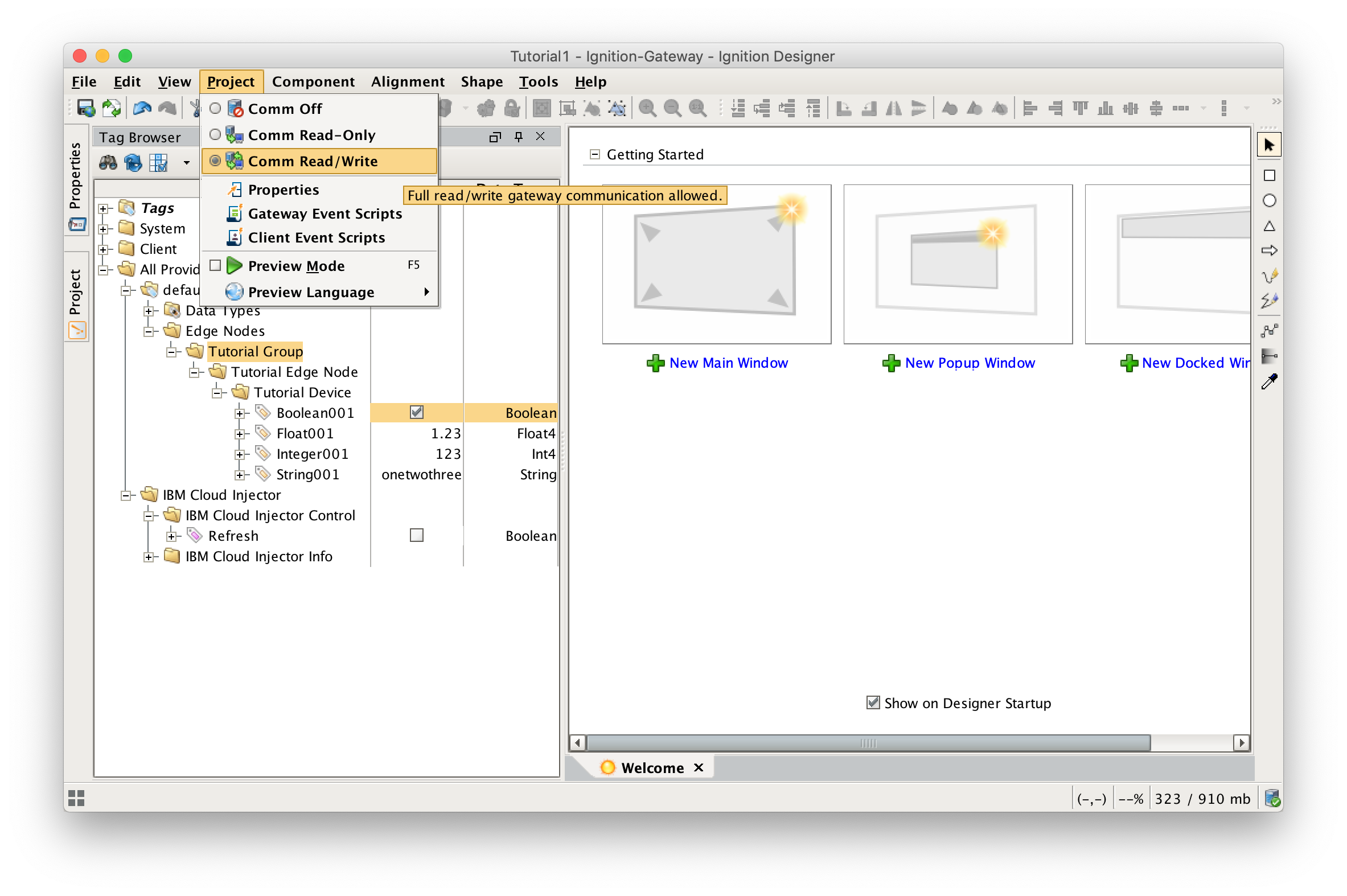
Now that we have a folder structure with some tags we can refresh the IBM Cloud Injector module. Make sure that the Ignition Designer has read/write communications turned on by selecting Project/Comm Read/Write.
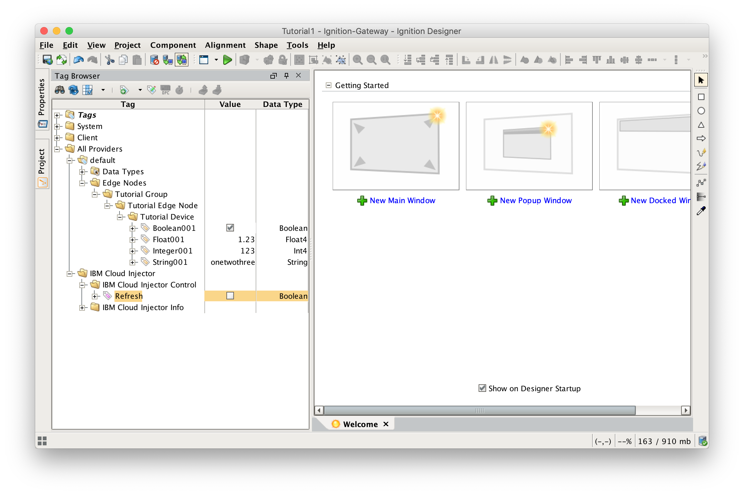
To refresh the default Tag Agent with the folder structure we’ve created, open the folder "All Providers/IBM Cloud Injector/IBM Cloud Injector Control" and click on the Refresh Boolean. Note the Boolean tag will not change to true. This is really a one-shot and as a result, the tag will not change to true.
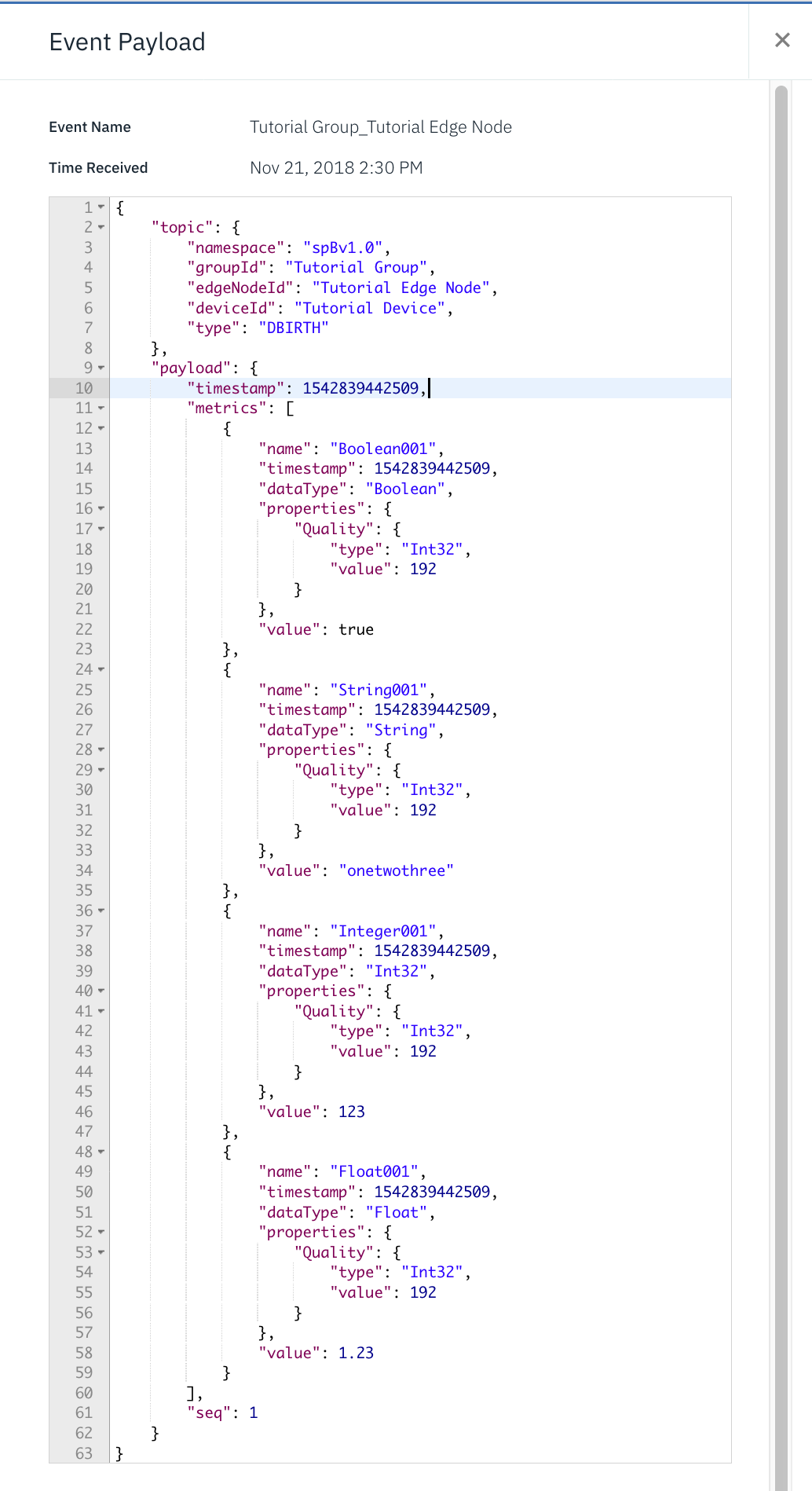
When this happens, the Tag Agent will scan the "Edge Nodes" folder and find the new Memory Tags that we have created, construct JSON payloads representing those tags with their current values and publish the payload to the IBM Cloud that has been configured.
The IBM Cloud Injector Tag Agent will publish two JSON payloads to the IBM Cloud. The format of these messages closely follows the Sparkplug B Specification's payload structure.
The first payload represents the Edge Node and will contain the following:
It will look something like this in the IBM Watson IoT Platform:

The second payload represents the Device and will contain the following:
It will look something like this:
